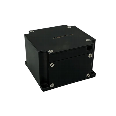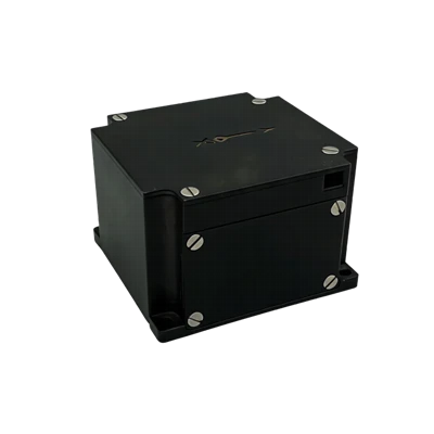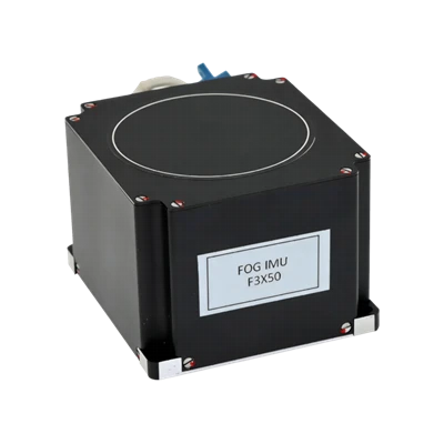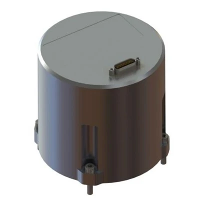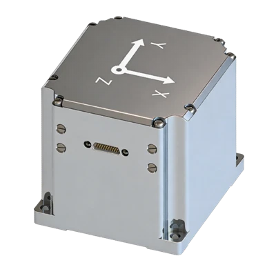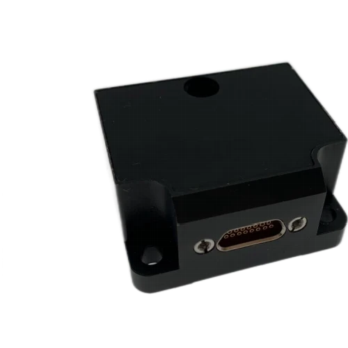
MSU203 MEMS Inertial Measurement Unit
Excellent resistance to harsh mechanical environments
Support for on-board software upgrade
Pin-to-pin replacement for STIM300
Description
Main Features
- 100% domestically manufactured components
- High-speed sampling capability
- Excellent resistance to harsh mechanical environments
- Support for on-board software upgrade
- Pin-to-pin replacement for STIM300
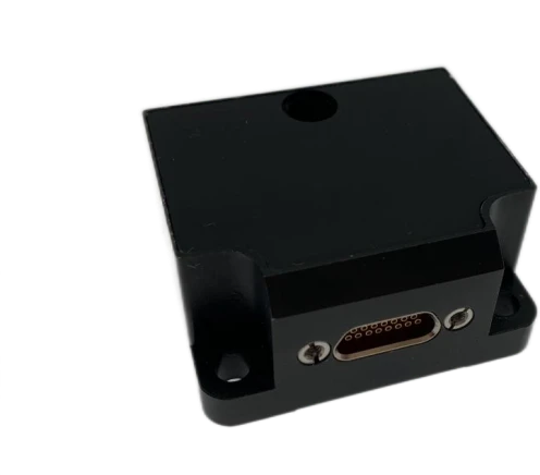
Application Fields
 UAV attitude reference & trajectory control
 Vehicle and ship attitude measurement
 Port measurement systems
 Mobile mapping systems
 Automated driving test systems
 Personal navigation systems
Product Overview
The MSU203 MEMS inertial measurement module is a high-reliability, cost-effective six-axis MEMS inertial measurement unit (IMU). It is widely applied in navigation, control and measurement fields represented by vehicles, ships and UAVs. The whole system adopts fully domestically manufactured electronic components. The built-in gyroscopes and accelerometers adopt state-of-the-art domestically produced MEMS inertial sensor technology. Customized hardware and software configurations are available for the MSU203 series inertial measurement modules to satisfy diverse user demands.
Unique Technology
Company is a high-tech enterprise with full closed-loop capabilities from fiber winding to FOGs, fiber/MEMS inertial products, IMU circuits, software, and test equipment. End-to-end process control improves quality and reduces costs. Operating under ISO9001, it ensures reliability and consistency.
MSU203 MEMS Inertial Measurement Unit
MSU203 MEMS Inertial Measurement Unit Performance Parameters
|
Parameter |
Technical Index |
|
Gyroscope |
|
|
Measurement Range (°/s) |
±500 |
|
Full-Temperature Bias (°/h, 3σ) |
≤30 |
|
Bias Stability (°/h, 10s averaging window) |
≤2 |
|
Bias Instability (°/h, Allan variance, typical) |
≤0.1 |
|
Bias Repeatability (°/h) |
≤1 |
|
Angular Random Walk (°/√h) |
≤0.1 |
|
Scale Factor Nonlinearity (ppm) |
≤100 |
|
Cross-Coupling Error (rad) |
≤0.001 |
|
Bandwidth (Hz) |
≥200 Hz |
|
Accelerometer |
|
|
Measurement Range (g) |
±30 |
|
Full-Temperature Bias (mg, 3σ) |
≤2 |
|
Bias Stability (μg, 10s averaging window) |
≤50 |
|
Bias Instability (μg, Allan variance, typical) |
≤30 |
|
Bias Repeatability (μg) |
≤50 |
|
Velocity Random Walk (m/s/√h) |
≤0.03 |
|
Scale Factor Nonlinearity (ppm, ±1g input) |
≤100 |
|
Cross-Coupling Error (rad) |
≤0.001 |
|
Bandwidth (Hz) |
≥200 Hz |
|
Physical Characteristics |
|
|
Maximum Data Update Rate (Hz) |
2000 |
|
Overall Dimension (mm×mm×mm) |
44.8×38.6×21.5 |
|
Weight (g) |
52±5 |
|
Operating Environment |
|
|
Operating Temperature (℃) |
-40 ~ 80 |
|
Storage Temperature (℃) |
-55 ~ 85 |
|
Vibration (g, RMS, 20~2000 Hz) |
6.06 |
|
Shock (g, 1 ms half-sine pulse) |
500 |
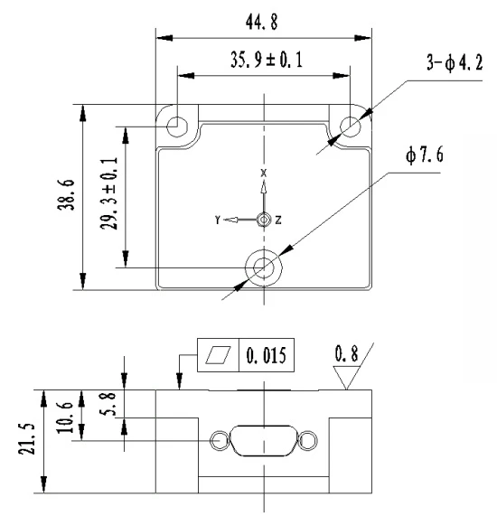
Dimensional Drawing
Product Introduction
Product Overview
The MSU203 MEMS inertial measurement module is a high-reliability, cost-effective six-axis MEMS inertial measurement unit (IMU). It is widely applied in navigation, control and measurement fields represented by vehicles, ships and UAVs. The whole system adopts fully domestically manufactured electronic components. The built-in gyroscopes and accelerometers adopt state-of-the-art domestically produced MEMS inertial sensor technology. Customized hardware and software configurations are available for the MSU203 series inertial measurement modules to satisfy diverse user demands.
Product Features
- 100% domestically manufactured components
- High performance, compact size, light weight and low power consumption
- Full-temperature calibration and compensation from -40℃ to +80℃
- High-speed sampling capability
- Excellent resistance to harsh mechanical environments
- Support for on-board software upgrade
- Pin-to-pin replacement for STIM300
Application Fields
- Antenna stabilization platforms
- UAV attitude reference & trajectory control
- Flight control systems
- Vehicle and ship attitude measurement
- Port measurement systems
- Mobile satellite communication terminals
- Mobile mapping systems
- Automated driving test systems
- Personal navigation systems
Technical Specifications
Table 1 Performance Parameters of MSU203 Inertial Measurement Module
|
Parameter |
Technical Index |
|
Gyroscope |
|
|
Measurement Range (°/s) |
±500 |
|
Full-Temperature Bias (°/h, 3σ) |
≤30 |
|
Bias Stability (°/h, 10s averaging window) |
≤2 |
|
Bias Instability (°/h, Allan variance, typical) |
≤0.1 |
|
Bias Repeatability (°/h) |
≤1 |
|
Angular Random Walk (°/√h) |
≤0.1 |
|
Scale Factor Nonlinearity (ppm) |
≤100 |
|
Cross-Coupling Error (rad) |
≤0.001 |
|
Bandwidth (Hz) |
≥200 Hz |
|
Accelerometer |
|
|
Measurement Range (g) |
±30 |
|
Full-Temperature Bias (mg, 3σ) |
≤2 |
|
Bias Stability (μg, 10s averaging window) |
≤50 |
|
Bias Instability (μg, Allan variance, typical) |
≤30 |
|
Bias Repeatability (μg) |
≤50 |
|
Velocity Random Walk (m/s/√h) |
≤0.03 |
|
Scale Factor Nonlinearity (ppm, ±1g input) |
≤100 |
|
Cross-Coupling Error (rad) |
≤0.001 |
|
Bandwidth (Hz) |
≥200 Hz |
|
Physical Characteristics |
|
|
Supply Voltage (V) |
5~12 (ripple ≤100 mV) |
|
Steady-State Power Consumption (W) |
≤2 |
|
Startup Time (s) |
≤2 |
|
Maximum Data Update Rate (Hz) |
2000 |
|
Overall Dimension (mm×mm×mm) |
44.8×38.6×21.5 |
|
Weight (g) |
52±5 |
|
Operating Environment |
|
|
Operating Temperature (℃) |
-40 ~ 80 |
|
Storage Temperature (℃) |
-55 ~ 85 |
|
Vibration (g, RMS, 20~2000 Hz) |
6.06 |
|
Shock (g, 1 ms half-sine pulse) |
500 |
Technical Specifications
Structural Characteristics
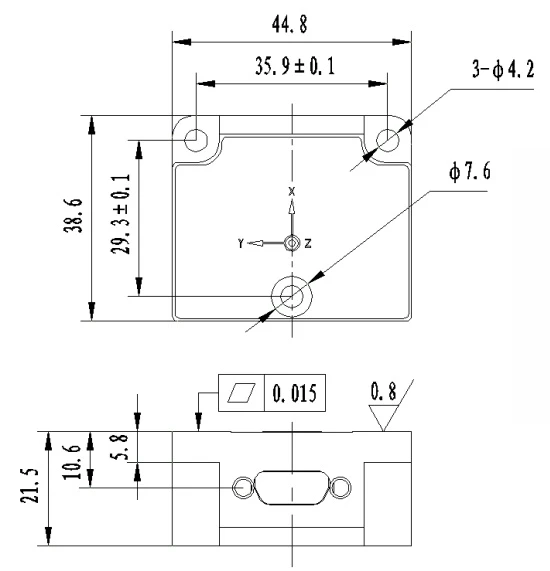
Figure 1 Overall Dimensions
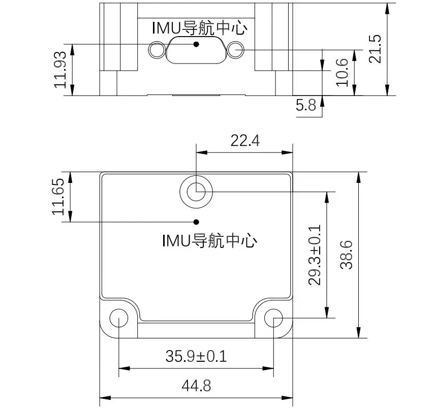
Figure 2 IMU Navigation Center Position
Product Marking and Coordinate Polarity
During product installation, the carrier coordinate system of the module shall maintain a fixed geometric relationship with the carrier coordinate system of the host equipment. The carrier coordinate system definition of the MSU203 MEMS inertial measurement module is shown in Figure 3.
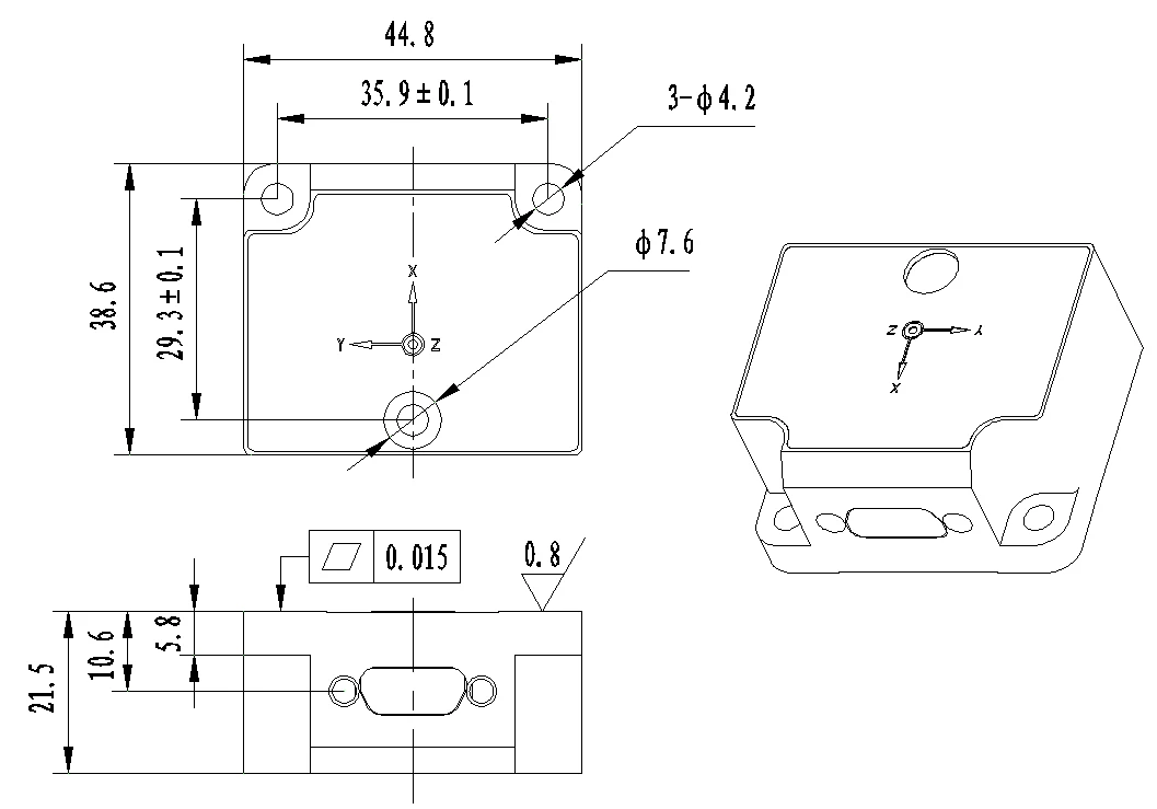
Figure 3 Product Coordinate System
Pin Assignment
The external connector of MSU203 inertial measurement module is J30J-15ZK, with mating connector model J30J-15TJL. It provides power supply and external communication interfaces. The pin definitions are listed in Table 2.
Table 2 External Pin Definition of MSU203 Inertial Measurement Module Connector
|
Pin No. |
Definition |
Remarks |
|
8 |
POWER_IN |
Power supply range: 5 V ~ 12 V (output ripple ≤ 100 mV) |
|
15 |
GND |
|
|
6 |
RS232_TXD1 |
RS232 communication interface |
|
5 |
RS232_RXD1 |
|
|
3 |
GND |
|
|
10 |
RS422 R+ |
M1: RS422 communication interface |
|
2 |
RS422 R- |
|
|
9 |
RS422 T+ |
|
|
1 |
RS422 T- |
|
|
14 |
RS232_TXD2 |
M2: RS232 communication interface, supports external GNSS module input for timestamp tagging |
|
7 |
RS232_RXD2 |
|
|
13 |
GND |
|
|
11 |
PPS_IN |
|
|
4 |
TOV |
General-purpose IO port, 3.3 V logic level, rising edge active |
|
12 |
GND |
After the supply voltage drops below the device operating threshold, the power-off holding time t_OFF before re-powering shall not be less than 3 seconds. Insufficient power-off interval may lead to abnormal startup, latch-up or initialization failure of the module.
External Communication
The MSU203 outputs data via M1 RS422 port by default, and supports multiple communication protocols as follows.
3.4.1 XDIMU-55AA Protocol
This protocol adopts periodic broadcast data output mode. Each frame consists of 1 start bit, 8 data bits and 1 stop bit without parity bit, transmitted in little-endian byte order. The default output rate is 200 Hz with baud rate 115200 bps. Baud rate and output frequency are user-configurable. The module outputs TOV synchronization pulses synchronized with IMU sampling frequency by default. When internal timestamp function is enabled, an external GNSS receiver shall be connected. The GNSS serial baud rate is fixed at 9600 bps, supporting GPRMC sentences (compatible with GNRMC / GBRMC). PPS input is TTL level with 1s period, synchronized on rising or falling edge. The IMU output frames will carry timestamp information, as shown in Table 3.
Table 3 XDIMU-55AA Frame Format of MSU203 MEMS Inertial Measurement Module
|
Byte Offset |
Definition |
Remarks |
|
1 |
Frame Header |
0x55 |
|
2 |
Frame Header |
0xAA |
|
3 |
Payload Length |
N−4 |
|
4 ~ N−1 |
Payload Data |
- |
|
N |
Checksum |
checksum byte |
|
Note: The checksum byte stores the lower 8 bits of the cumulative sum of payload length and all payload bytes. |
||
Table 4 XDIMU-55AA Payload Definition of MSU203 MEMS Inertial Measurement Module
|
Index |
Start Byte Offset |
Byte Count |
Content |
Scale Factor |
Range |
Unit |
Remarks |
|
1 |
0 |
1 |
0 |
1 |
0x55 |
1 |
- |
|
2 |
1 |
1 |
0xAA |
1 |
- |
- |
Frame header |
|
3 |
2 |
1 |
0x36 |
1 |
- |
- |
Payload length |
|
4 |
3 |
4 |
PCnum |
1 |
- |
- |
1 millisecond counter |
|
5 |
7 |
4 |
X Angular Rate |
0.000001 |
[-1000, 1000] |
°/s |
- |
|
6 |
11 |
4 |
Y Angular Rate |
0.000001 |
[-1000, 1000] |
°/s |
- |
|
7 |
15 |
4 |
Z Angular Rate |
0.000001 |
[-1000, 1000] |
°/s |
- |
|
8 |
19 |
4 |
X Acceleration |
0.000001 |
[-40, 40] |
m/s² |
- |
|
9 |
23 |
4 |
Y Acceleration |
0.000001 |
[-40, 40] |
m/s² |
- |
|
10 |
27 |
4 |
Z Acceleration |
0.000001 |
[-40, 40] |
m/s² |
- |
|
11 |
31 |
2 |
Temperature |
0.008 |
[-120, 120] |
℃ |
- |
|
12 |
33 |
2 |
Year-Month-Day |
- |
- |
- |
Bit0~Bit4: Day (0~31)Bit5~Bit8: Month (0~12)Bit9~Bit15: Year (0~99)Example binary 1100011110011111 = 31 Dec, 2099 |
|
13 |
35 |
4 |
Timestamp |
0.1 |
- |
ms |
Calculation formula: (Hour×3600 + Minute×60 + Second) × 10000Example binary string corresponds to 23:59:59.9999 |
|
14 |
39 |
1 |
Checksum |
1 |
[0, 255] |
- |
Lower 8 bits of cumulative sum of bytes offset 2 ~ 38 |
3.4.2 STIMIMU-A5 Protocol
This protocol uses periodic broadcast transmission, baud rate 115200 bps, 8 data bits, 1 stop bit, no parity bit, user-configurable refresh rate defaulted to 200 Hz. Data is transmitted in big-endian byte order. The full frame structure is shown in Table 5.
Table 5 STIMIMU-A5 Communication Protocol of MSU203 MEMS Inertial Measurement Module
|
Frame Offset |
Data Type |
Scale Factor |
Unit & Description |
|
Byte 0 |
0xA5 |
- |
- |
|
Byte 1 ~ Byte 3 |
X-axis gyro angular rate(24-bit two's complement, big-endian) |
2⁻¹⁴ |
Unit: °/s |
|
Byte 4 ~ Byte 6 |
Y-axis gyro angular rate(24-bit two's complement, big-endian) |
2⁻¹⁴ |
Same as X-axis gyro angular rate |
|
Byte 7 ~ Byte 9 |
Z-axis gyro angular rate(24-bit two's complement, big-endian) |
2⁻¹⁴ |
Same as X-axis gyro angular rate |
|
Byte 10 |
Gyro Status Byte |
- |
Reserved as 0 |
|
Byte 11 ~ Byte 13 |
X-axis accelerometer data(24-bit two's complement, big-endian) |
2⁻¹⁸ |
Unit: g |
|
Byte 14 ~ Byte 16 |
Y-axis accelerometer data(24-bit two's complement, big-endian) |
2⁻¹⁸ |
Same as X-axis accelerometer data |
|
Byte 17 ~ Byte 19 |
Z-axis accelerometer data(24-bit two's complement, big-endian) |
2⁻¹⁸ |
Same as X-axis accelerometer data |
|
Byte 20 |
Accelerometer Status Byte |
- |
Reserved as 0 |
|
Byte 21 ~ Byte 22 |
X-axis gyro temperature(16-bit two's complement, big-endian) |
2⁻⁸ |
Unit: ℃ |
|
Byte 23 ~ Byte 24 |
Y-axis gyro temperature(16-bit two's complement, big-endian) |
2⁻⁸ |
Same as X-axis gyro temperature |
|
Byte 25 ~ Byte 26 |
Z-axis gyro temperature(16-bit two's complement, big-endian) |
2⁻⁸ |
Same as X-axis gyro temperature |
|
Byte 27 |
Gyro Temperature Status Byte |
- |
Reserved as 0 |
|
Byte 28 ~ Byte 29 |
X-axis accelerometer temperature(16-bit two's complement, big-endian) |
2⁻⁸ |
Unit: ℃ |
|
Byte 30 ~ Byte 31 |
Y-axis accelerometer temperature(16-bit two's complement, big-endian) |
2⁻⁸ |
Same as X-axis accelerometer temperature |
|
Byte 32 ~ Byte 33 |
Z-axis accelerometer temperature(16-bit two's complement, big-endian) |
2⁻⁸ |
Same as X-axis accelerometer temperature |
|
Byte 34 |
Accelerometer Temperature Status Byte |
- |
Reserved as 0 |
|
Byte 35 |
Frame Counter (cyclic from 0 to 255) |
- |
2 kHz sampling frequency |
|
Byte 36 ~ Byte 37 |
Data Update Interval(16-bit unsigned integer, big-endian) |
- |
Unit: microsecond per frame |
|
Byte 38 ~ Byte 41 |
CRC32(32-bit unsigned integer, big-endian) |
- |
- |


Status Bit Definition:
Table 6 Status Bit Definition
|
Bit Index |
Definition |
|
Bit 7 |
0 = Normal, 1 = Global system fault |
|
Bit 6 |
0 = Normal, 1 = Startup ongoing |
|
Bit 5 |
0 = Normal, 1 = Abnormal external environment |
|
Bit 4 |
0 = Normal, 1 = All axes out of operating range |
|
Bit 3 |
0 = Normal, 1 = Three-axis output error |
|
Bit 2 |
0 = Normal, 1 = Z-axis overrange / fault |
|
Bit 1 |
0 = Normal, 1 = Y-axis overrange / fault |
|
Bit 0 |
0 = Normal, 1 = X-axis overrange / fault |
CRC Calculation Method:
The CRC checksum is used to detect errors generated during data transmission.
CRC Polynomial:


All preceding data (including frame header identifier) shall be involved in CRC calculation.
The CRC algorithm requires complete 32-bit (4-byte) data blocks. Several data frame formats defined by MSU203 have lengths that are not integer multiples of 4 bytes.
To optimize transmission efficiency and avoid sending meaningless padding bytes, virtual bytes filled with 0x00 shall be appended to the end of the frame when computing the CRC of the last byte.
3.4.3 STIMIMU-94 Protocol
Periodic broadcast transmission, baud rate 115200 bps, 8 data bits, 1 stop bit, no parity, refresh rate default 200 Hz, big-endian transmission order. Frame definition shown in Table 7.
Table 7 STIMIMU-94 Communication Protocol of MSU203 MEMS Inertial Measurement Module
|
Frame Offset |
Data Type |
Scale Factor |
Unit & Detailed Description |
|
Byte 0 |
0x94 |
- |
- |
|
Byte 1 ~ Byte 3 |
X-axis gyro angular rate increment(24-bit two's complement, big-endian) |
2⁻²¹ |
Unit: °/s |
|
Byte 4 ~ Byte 6 |
Y-axis gyro angular rate increment(24-bit two's complement, big-endian) |
2⁻²¹ |
Consistent with X-axis gyro angular rate increment |
|
Byte 7 ~ Byte 9 |
Z-axis gyro angular rate increment(24-bit two's complement, big-endian) |
2⁻²¹ |
Consistent with X-axis gyro angular rate increment |
|
Byte 10 |
Gyro Status Byte |
- |
Gyro measurement status word, refer to the corresponding table |
|
Byte 11 ~ Byte 13 |
X-axis gyro temperature(16-bit two's complement, big-endian) |
2⁻⁸ |
Unit: ℃ |
|
Byte 14 ~ Byte 16 |
Y-axis gyro temperature(16-bit two's complement, big-endian) |
2⁻⁸ |
Consistent with X-axis gyro temperature |
|
Byte 17 ~ Byte 19 |
Z-axis gyro temperature(16-bit two's complement, big-endian) |
2⁻⁸ |
Consistent with X-axis gyro temperature |
|
Byte 20 |
Gyro temperature measurement status byte |
- |
All bits set to 0 indicates normal state, detailed definition shown in the corresponding table |
|
Byte 21 |
Frame counter (cyclic range: 0~255) |
- |
2 kHz sampling frequency |
|
Byte 22 ~ Byte 23 |
Data update interval(16-bit unsigned integer, big-endian) |
- |
Unit: microsecond per frame |
|
Byte 24 ~ Byte 27 |
Checksum(32-bit unsigned integer, big-endian) |
- |
- |


Table 8 Bit Definition
|
Bit Index |
Definition |
|
7 |
0 = Normal, 1 = Global system fault |
|
6 |
0 = Normal, 1 = Startup in progress |
|
5 |
0 = Normal, 1 = Abnormal external environment |
|
4 |
0 = Normal, 1 = All axes out of operating range |
|
3 |
0 = Normal, 1 = Three-axis output error |
|
2 |
0 = Normal, 1 = Z-axis overrange / fault |
|
1 |
0 = Normal, 1 = Y-axis overrange / fault |
|
0 |
0 = Normal, 1 = X-axis overrange / fault |
3.4.4 HCIMU-AA55 Protocol
This protocol adopts periodic broadcast data transmission with little-endian byte order (LSB first). Serial communication parameters: baud rate 115200 bps, 8 data bits, 1 stop bit, no parity bit; the default refresh rate is 200 Hz (configurable). The frame format is shown in the tables below.
Table 9 HCIMU-AA55 Format for MSU203 MEMS Inertial Measurement Module
|
No. |
Rule |
Content |
Remarks |
|
1 |
Frame structure |
Header + Payload + CRC32 Checksum |
- |
|
2 |
Byte order |
Little-endian |
- |
|
3 |
CRC32 Parameter |
CRC32 polynomial: x32+x26+x23+x22+x16+x12+x11+x10+x8+x7+x5+x4+x2+x+1Reversed polynomial constant: 0xEDB88320 |
- |
|
4 |
Scale calculation rule |
True value = Raw data × Scale factor |
- |
|
5 |
Offset calculation rule |
True value = Raw data × Scale factor + Offset |
- |
Notes:
- No offset is adopted in this product, offset value shall be filled with 0.
- CRC calculation covers frame header and payload with initial seed value 0.
- The header shall be parsed according to above rules; fixed message ID: 0x0106.
Table 10 HCIMU-AA55 Communication Payload of MSU203 MEMS Inertial Measurement Module
|
No. |
Short Message Name |
ID |
Description |
Category |
Remarks |
|
1 |
HCRAWIMUXSB |
0x0106 |
Raw acceleration, angular rate and attitude data under device coordinate system |
Raw inertial data |
General-purpose |
Table 11 HC Short Header
|
No. |
Name |
Data Type |
Description |
Byte Count |
Byte Offset |
|
1 |
Sync |
Char |
0xAA |
1 |
0 |
|
2 |
Sync |
Char |
0x55 |
1 |
0 |
|
3 |
Sync |
Char |
ASCII 'H' (0x48) |
1 |
0 |
|
4 |
Sync |
Char |
ASCII 'C' (0x43) |
1 |
0 |
|
5 |
Message Length |
Ushort |
Actual payload length excluding header and CRC |
2 |
0 |
|
6 |
Message ID |
Ushort |
Message identifier |
2 |
0 |
Table 11 HCRAWIMUXSB (Device Coordinate System)
|
No. |
Name |
Data Type |
Description |
Scale Factor |
Byte Count |
Byte Offset |
|
1 |
HC Short header |
Struct |
Frame header (ID, length, timestamp, serial number, etc.) |
N/A |
8 |
0 |
|
2 |
Time_s |
Double |
Sampling time, unit: s |
1 |
8 |
8 |
|
3 |
gyro_x |
Int |
X-axis angular rate, unit: °/s |
Configured via ImuType |
4 |
16 |
|
4 |
gyro_y |
Int |
Y-axis angular rate, unit: °/s |
Configured via ImuType |
4 |
20 |
|
5 |
gyro_z |
Int |
Z-axis angular rate, unit: °/s |
Configured via ImuType |
4 |
24 |
|
6 |
acc_x |
Int |
X-axis acceleration, unit: g |
Configured via ImuType |
4 |
28 |
|
7 |
acc_y |
Int |
Y-axis acceleration, unit: g |
Configured via ImuType |
4 |
32 |
|
8 |
acc_z |
Int |
Z-axis acceleration, unit: g |
Configured via ImuType |
4 |
36 |
|
9 |
pitch |
Float |
Pitch angle, range ±90 ° |
1 |
4 |
40 |
|
10 |
roll |
Float |
Roll angle, range ±180 ° |
1 |
4 |
44 |
|
11 |
yaw |
Float |
Yaw angle, range 0~360 ° |
1 |
4 |
48 |
|
12 |
temp |
Short |
IMU internal temperature, unit: ℃ |
0.01 |
2 |
52 |
|
13 |
ErrStatus |
Uchar |
Fault status flag |
N/A |
1 |
54 |
|
14 |
SysStatus |
Uchar |
System status flag |
N/A |
1 |
55 |
|
15 |
ImuType |
Uchar |
IMU mode identifier |
N/A |
1 |
56 |
|
16 |
Receiver |
Uchar |
Reserved byte |
N/A |
1 |
57 |
|
17 |
CRC32 |
Uint |
32-bit CRC check value |
N/A |
4 |
58 |
|
62 |
Table 12 ErrStatus Bit Definition
|
No. |
Name |
Bit Width |
Description |
Bit Offset |
No. |
|
1 |
Receiver |
1 |
Reserved |
0 |
1 |
|
2 |
Status_gyro_x |
1 |
0 = Normal; 1 = Fault |
1 |
2 |
|
3 |
Status_gyro_y |
1 |
0 = Normal; 1 = Fault |
2 |
3 |
|
4 |
Status_gyro_z |
1 |
0 = Normal; 1 = Fault |
3 |
4 |
|
5 |
Receiver |
1 |
Reserved |
4 |
5 |
|
6 |
Status_acc_x |
1 |
0 = Normal; 1 = Fault |
5 |
6 |
|
7 |
Status_acc_y |
1 |
0 = Normal; 1 = Fault |
6 |
7 |
|
8 |
Status_acc_z |
1 |
0 = Normal; 1 = Fault |
7 |
8 |
Table 13 SysStatus Bit Definition
|
No. |
Name |
Bit Width |
Description |
Bit Offset |
No. |
|
1 |
TimeStatus |
3 |
Time synchronization state0x0: No PPS & no RMC & no internal clock, timestamp invalid (non-occurring)0x1: No PPS & no RMC, internal crystal timing0x2: PPS available without RMC (1) No initial timestamp: accumulate from 0s (2) Initial timestamp exists: accumulate from current time0x3: Both PPS and RMC valid (non-occurring)0x4: Internal GNSS reference time (combined unit only)0x5~0x7: Reserved |
0 |
1 |
|
2 |
YawMode |
2 |
Heading alignment mode0x0: Zero initial alignment0x1: Magnetometer alignment0x2: Gyro north-seeking alignment0x3: External heading injection |
3 |
2 |
|
3 |
SolStatus |
3 |
Attitude solution state0x0: Normal solution0x1~0x7: Solution fault (reserved) |
5 |
3 |
Note: If no PPS signal is detected for 10 consecutive seconds, PPS is regarded as lost; if no RMC sentence is parsed for 10 consecutive seconds, RMC is regarded as lost.
Table 14 ImuType Definition
|
ImuType Value |
Mode Name |
Description |
|
0 |
ImuType_High_Accuracy |
General high-precision IMUGyro range: ±500 °/s, Scale factor = 2.5×10⁻⁷ °/sAccelerometer range: ±20 g, Scale factor = 1×10⁻⁸ g |
|
1 |
ImuType_High_Range |
General wide-range IMUGyro range: ±2000 °/s, Scale factor = 1×10⁻⁶ °/sAccelerometer range: ±200 g, Scale factor = 1×10⁻⁷ g |
|
2 ~ 255 |
Reserved |
Unused identifier |
Supplementary Notes:
Standard gravitational acceleration g = 9.80665 m/s².
This module only adopts ImuType_High_Accuracy; ImuType_High_Range is not used.
Pitch, roll and yaw output default to 0; ErrStatus and SysStatus default to 0.
Timing rule: Internal interrupt counter is used without PPS input; timestamp will align to integer second upon the first PPS trigger.
CRC calculation code is shown below.
3.4.5 MTIMU-BDDB Protocol
This protocol adopts periodic broadcast data transmission, with data transmitted in little-endian byte order (least significant byte first). Serial communication parameters: baud rate 115200 bps, 8 data bits, 1 stop bit, no parity bit. The default data refresh rate is 200 Hz (configurable). The output frame format is defined in the table below.
Table 15 MTIMU-BDDB Format for MSU203 MEMS Inertial Measurement Module
|
Byte |
Value |
Value Type |
Description |
|
0 |
0xBD |
Fixed value |
|
|
1 |
0xDB |
||
|
2 |
0x0A |
||
|
3~6 |
LSB |
Float |
Gx |
|
MID1 |
Factor1 |
||
|
MID2 |
Unit deg/s |
||
|
MSB |
|||
|
7~10 |
LSB |
Float |
Gy |
|
MID1 |
Factor1 |
||
|
MID2 |
Unit deg/s |
||
|
MSB |
|||
|
11~14 |
LSB |
Float |
Gz |
|
MID1 |
Factor1 |
||
|
MID2 |
Unit deg/s |
||
|
MSB |
|||
|
15~18 |
LSB |
Float |
Ax |
|
MID1 |
Factor1 |
||
|
MID2 |
Unit deg/s |
||
|
MSB |
|||
|
19~22 |
LSB |
Float |
Ay |
|
MID1 |
Factor1 |
||
|
MID2 |
Unit deg/s |
||
|
MSB |
|||
|
23~26 |
LSB |
Float |
Az |
|
MID1 |
Factor1 |
||
|
MID2 |
Unit deg/s |
||
|
MSB |
|||
|
27 |
LSB |
Signed |
Temperature |
|
Factor 0.006 |
|||
|
Minimun-60 |
|||
|
Maximum+125 |
|||
|
28 |
MSB |
Unit ℃ |
|
|
29 |
BIT |
UnSigned |
Built in Test (default: 0x00) |
|
30 |
Reserved |
Reserved |
Reserved (default: 0x00) |
|
31 |
LSB |
UnSigned |
Counter |
|
Factor1 |
|||
|
Minimun 0 |
|||
|
Maximum 65535 |
|||
|
32 |
MSB |
Unit ms |
|
|
33 |
Check |
Byte |
XOR checksum, covering Byte 0 to Byte 32 |
Remarks: The 2-byte counter is an integer with unit millisecond. The hardware interrupt period is 0.5 ms, and the output value is rounded up.
3.4.6 MPIMU-55 Protocol
This protocol transmits data in periodic broadcast mode with little-endian byte order (LSB first). Communication parameters: baud rate 115200 bps, 8 data bits, 1 stop bit, no parity bit; the default refresh rate is 200 Hz (configurable).
When internal time synchronization is enabled, an external GNSS receiver shall be connected. The GNSS serial baud rate is 9600 bps, supporting GPRMC sentences (compatible with GNRMC / GBRMC). The PPS signal is TTL level with a 1-second cycle, synchronized on rising edge or falling edge by default. Under this configuration, the IMU output frames carry timestamp information.
The frame format is shown in the table below:
Table 16 MPIMU-55AC Format for MSU203 MEMS Inertial Measurement Module
|
Byte Offset |
Data Type |
Description |
|
0 |
U8 |
Header 0x55 |
|
1 |
U8 |
Header 0xAC |
|
2~3 |
U16 |
GPS Week |
|
4~11 |
double |
m-second |
|
12~15 |
float |
Gyro X, deg/s |
|
16~19 |
float |
Gyro Y, deg/s |
|
20~23 |
float |
Gyro Z, deg/s |
|
24~27 |
float |
ACC X, m/s2 |
|
28~31 |
float |
ACC Y, m/s2 |
|
32~35 |
float |
ACC Z, m/s2 |
|
36~37 |
U16 |
ODO count |
|
38~39 |
U16 |
CAN BUS DATA,0.01m/s |
|
40~41 |
I16 |
Temperature, 0.5°/LSB |
|
42 |
U8 |
IMU status |
|
43 |
U8 |
Checksum, unsigned char adding from Byte2~Byte42 |
|
115200-8-N-1, little-endian, output rate: 200Hz |
||
Remarks:
1. IMU Status Bit Definition
Bit1 PPS: 0 = Normal, 1 = Fault. Once valid PPS signal is detected, this bit locks to 0 and will not flip to 1 again.
Bit2 Time(SOW): 0 = Normal, 1 = Fault. Once valid SOW data is received, this bit locks to 0 and will not flip to 1 again.
Bit3 IMU1: 0 = Normal, 1 = Fault
Bit4 IMU2 error (if equipped): 0 = Normal, 1 = Fault
Bit6 CAN bus: 0 = Normal, 1 = Fault
Bit7~8 Motion Status: 0 = Static, 1 = Mild motion, 2 = Medium motion, 3 = Severe motion
Raw data adopts Right-Front-Up coordinate system and outputs angular rate; after decoding, data is converted to Front-Down-Right frame and outputs angular increment & velocity increment.
If no satellite lock at power-on, GPS Week value is set to 0 and millisecond counter increments sequentially. After satellite signal becomes valid, GPS Week and millisecond value will synchronize with GNSS receiver board.
3.4.7 NVIMU-AA44 Protocol
This protocol outputs data in periodic broadcast mode with little-endian byte order (LSB transmitted first). Serial parameters: baud rate 115200 bps, 8 data bits, 1 stop bit, no parity bit; default refresh rate 200 Hz (configurable).
When internal time synchronization is enabled, an external GNSS receiver shall be connected. The GNSS serial baud rate is 9600 bps, supporting GPRMC sentences (compatible with GNRMC / GBRMC). PPS signal is TTL level with 1s period, synchronized on rising edge or falling edge by default. Timestamp will be embedded in IMU output frames under this configuration.
The frame format is shown in the table below:
Table 17 NVIMU-AA44 Communication Payload for MSU203 MEMS Inertial Measurement Module
|
Index |
Name |
Data Type |
Description |
Byte Count |
Byte Offset |
|
1 |
Sync Header |
Char |
Hex value 0xAA |
1 |
0 |
|
2 |
Sync Header |
Char |
Hex value 0x44 |
1 |
1 |
|
3 |
Sync Header |
Char |
Hex value 0x13 |
1 |
2 |
|
4 |
Message Length |
Uchar |
Payload length excluding header and CRC |
1 |
3 |
|
5 |
Message ID |
Ushort |
Message identifier |
2 |
4 |
|
6 |
GNSS Week |
Ushort |
GNSS week number |
2 |
6 |
|
7 |
Milliseconds in GNSS Week |
GPSec |
Milliseconds elapsed from the start of GNSS week(Byte layout consistent with Long type) |
4 |
8 |
Note: Fixed Message ID = 1462
|
Index |
Name |
Description |
Data Type |
Byte Count |
Byte Offset |
|
1 |
RAWIMUSX Header |
Frame sync header |
Struct |
- |
H |
|
2 |
IMU Flag Bit |
IMU status flag bitsBit0: Flag set when IMU fault detected; refer to IMUStatus field for detailsBit1: Flag set when IMU data encrypted (data shall not be used)Bit2 ~ Bit7: Reserved |
Hex Uchar |
1 |
H |
|
3 |
IMU Type |
IMU mode identifier |
Uchar |
1 |
H+1 |
|
4 |
GNSS Week |
GNSS week count |
Ushort |
2 |
H+2 |
|
5 |
Seconds in GNSS Week |
Seconds within the current GNSS week |
Double |
8 |
H+4 |
|
6 |
IMU Status |
IMU operating status. This field is a fixed-length binary byte array, converted to 2-character hexadecimal in ASCII or abbreviated output format |
Hex Ulong |
4 |
H+12 |
|
7 |
Z Acceleration |
Change of velocity count for Z-axis |
Long |
4 |
H+16 |
|
8 |
Negative Y Acceleration |
Negative value of Y-axis velocity count changeNegative value: Output aligns with positive Y-axis marked on IMUPositive value: Variation direction opposite to the labeled positive Y-axis on IMU |
Long |
4 |
H+20 |
|
9 |
X Acceleration |
Change of velocity count for X-axis |
Long |
4 |
H+24 |
|
10 |
Z Angular Rate |
Change of angle count around Z-axis, right-hand coordinate system |
Long |
4 |
H+28 |
|
11 |
Negative Y Angular Rate |
Negative value of Y-axis angle count change, right-hand coordinate systemNegative value: Output aligns with positive Y-axis marked on IMUPositive value: Variation direction opposite to the labeled positive Y-axis on IMU |
Long |
4 |
H+32 |
|
12 |
X Angular Rate |
Change of angle count around X-axis, right-hand coordinate system |
Long |
4 |
H+36 |
|
13 |
CRC32 Checksum |
32-bit CRC value (supports ASCII, binary and short binary formats) |
Hex |
4 |
H+40 |
|
14 |
[CR][LF] |
Terminator (ASCII mode only) |
- |
- |
- |
Notes:
In this protocol, IMU Type = 0, IMU Status = 0x406
Accelerometer LSB = 1×10⁻⁶ m/s²; Gyro LSB = 1×10⁻⁶ °/s.
3.4.8 NVIMU-55AA Protocol
This protocol adopts periodic broadcast data transmission with little-endian byte order (least significant byte transmitted first). Communication parameters: baud rate 115200 bps, 8 data bits, 1 stop bit, no parity bit. The default data refresh rate is 200 Hz (configurable).
When internal time synchronization function is enabled, an external GNSS receiver shall be connected to the module. The GNSS serial baud rate is 9600 bps, supporting GPRMC sentences (compatible with GNRMC / GBRMC). The PPS signal is TTL level with a 1-second period, synchronized on rising edge or falling edge by default. Under this configuration, the IMU output frames carry timestamp information.
The frame format is defined in the table below.
Table 12 NVIMU-55AA Communication Payload of MSU203 MEMS Inertial Measurement Module
|
Byte Index |
Field Name |
Byte Count |
Description |
|
1 |
Frame Header 1 |
1 |
Fixed value: 0x55 |
|
2 |
Frame Header 2 |
1 |
Fixed value: 0xAA |
|
3~6 |
Seconds within GPS Week |
4 |
Unsigned integer, unit: s |
|
7~10 |
PPS Counter |
4 |
Unsigned integer, unit: 0.1 μs |
|
11~14 |
IMU Counter |
4 |
Unsigned integer, unit: 0.1 μs |
|
15~18 |
X Gyro Output |
4 |
Single-precision floating point, unit: °/s |
|
19~22 |
Y Gyro Output |
4 |
|
|
23~26 |
Z Gyro Output |
4 |
|
|
27~30 |
X Accelerometer Output |
4 |
Single-precision floating point, unit: m/s² |
|
31~34 |
Y Accelerometer Output |
4 |
|
|
35~38 |
Z Accelerometer Output |
4 |
|
|
39~40 |
Odometer |
2 |
Unsigned short integer, unit: 1 (may be used as status word) |
|
41~42 |
Temperature |
2 |
Signed short integer, unit: 0.1 ℃ |
|
43 |
Checksum |
1 |
Lower 8 bits of cumulative sum of Byte 3 ~ Byte 42 (Frame headers 0x55 and 0xAA excluded) |
Remarks:
- Output interface: RS422
- The PPS counter and IMU counter share the same internal clock source.
- The PPS counter records the value of the internal timer upon receiving each PPS pulse.
- Product Precautions
- Refer strictly to the product electrical pin definition and wire in accordance with the pin layout to prevent incorrect wiring.
- This product is a precision measuring device. Avoid subjecting it to shocks, collisions and other mechanical loads beyond its rated tolerance during handling.
- The mounting condition greatly affects angular rate measurement. The mounting surface shall have high flatness to eliminate installation misalignment error.
- The product shall be mounted firmly and reliably to prevent measurement errors caused by loose fitting.
- Anti-static protection shall be adopted during installation and operation; an anti-static wrist strap is recommended.
All operations shall comply fully with the requirements specified in this manual, and the ambient conditions shall meet the operating specifications. Do not disassemble the housing or alter the internal structure if a fault occurs. Contact our technical support engineers in a timely manner for assistance.
Hot Tags: msu203 mems inertial measurement unit, China msu203 mems inertial measurement unit manufacturers, factory