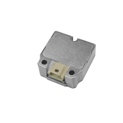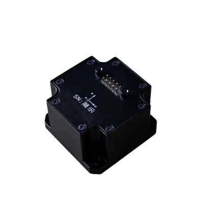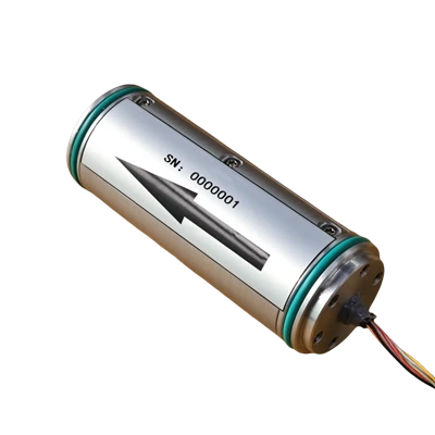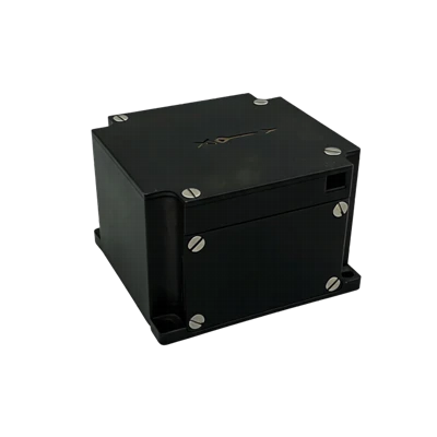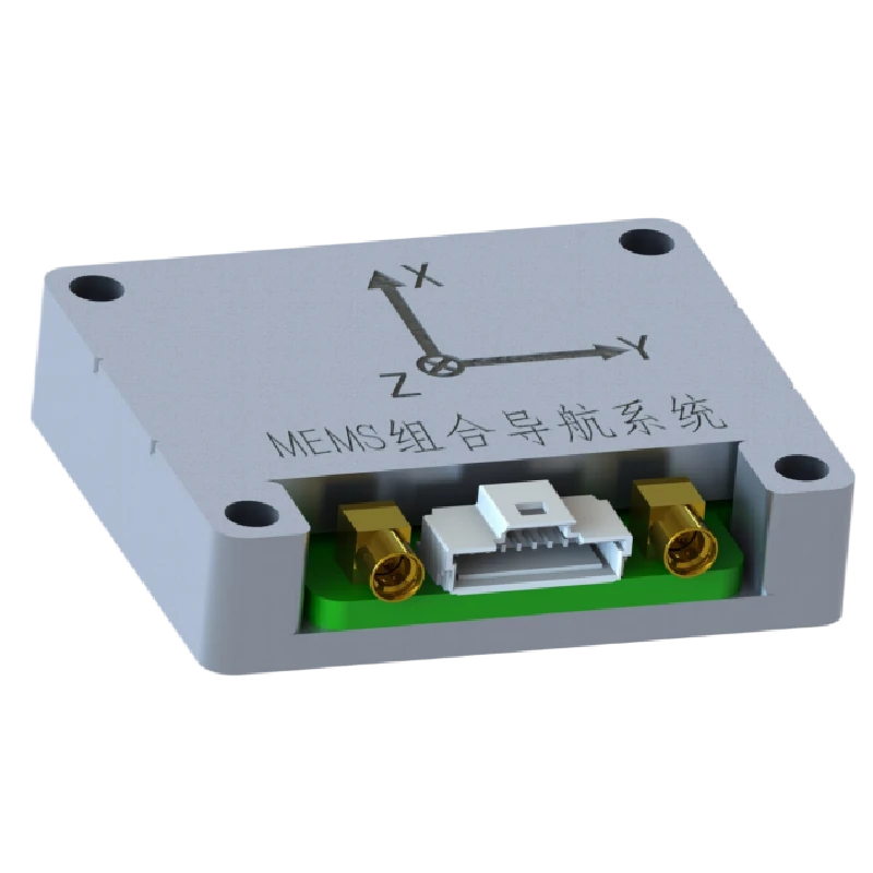
MSU105 Mini MEMS Integrated Inertial Navigation System
Full-band GNSS, high precision
Ultra-low power: 0.5 W
Adaptive AHRS (optional)
Description
Key Features
- High performance, compact size, lightweight
- Full-band GNSS, high precision
- Ultra-low power: 0.5 W
- Adaptive AHRS (optional)
- Full-temperature compensation (-45°C to 80°C)
- Online upgrade capability, lever-arm compensation
- Pure-inertial horizontal accuracy
- RTK differential support
Application
- Mobile mapping and engineering inspection
- Underwater high-precision navigation
- UAV attitude and flight control
- Vehicle and marine attitude reference
- SATCOM-on-the-move
Product Introduction
Company MSU105 is a miniature, cost-effective MEMS integrated inertial navigation system targeting SATCOM-on-the-move, UAVs, and similar navigation, control, and measurement applications. It tightly integrates MEMS sensors and a full-band GNSS receiver chip within a compact form factor, delivering precise positioning and attitude measurement in a small package.
Unique Technology
Company is a high-tech enterprise with full closed-loop capabilities from fiber winding equipment and coils to FOGs, fiber/MEMS inertial products, IMU circuits, software, and test equipment. End-to-end process control improves quality and reduces costs. Operating under ISO9001 with strict processes, it ensures product reliability and consistency.
MSU105 Mini MEMS Integrated Inertial System Specifications
|
Parameter |
MSU105 |
|
MEMS Gyroscope |
|
|
Range (°/s)° |
±300 |
|
Full-Temp. Bias (°/h)° |
≤360 |
|
Bias Stability (°/h, 10s avg.)° |
≤10 |
|
Bias Instability (°/h, Allan) |
≤3 |
|
Bias Repeatability (°/h)° |
≤10 |
|
Angular Random Walk (°/√h) |
≤0.3 |
|
Scale Factor Nonlinearity (ppm) |
≤100 |
|
Cross-Axis Coupling (rad) |
≤0.001 |
|
Bandwidth (Hz) |
≥100 |
|
MEMS Accelerometer |
|
|
Range (g) |
±16 |
|
Bias (mg) |
≤5 |
|
Bias Stability (µg, 10s avg.) |
≤300 |
|
Bias Stability (µg, Allan) |
≤50 |
|
Bias Repeatability (µg) |
≤300 |
|
Velocity Random Walk (mm/s/√h) |
≤50 |
|
Scale Factor Nonlinearity (ppm, ±1g) |
≤300 |
|
Cross-Axis Coupling (rad) |
≤0.001 |
|
Bandwidth (Hz) |
≥100 |
|
Integrated Navigation Accuracy |
|
|
Integrated Horizontal Position (m, 1σ) |
3 m (Single Point), 0.02+1 ppm (RTK) |
|
Integrated Vertical Position (m, 1σ) |
5 m (Single Point), 0.03+1 ppm (RTK) |
|
Integrated Horizontal Velocity (m/s, 1σ) |
0.1 |
|
Integrated Vertical Velocity (m/s, 1σ) |
0.15 |
|
Integrated Heading (°, 1σ, Real-Time) |
0.2 (1m Baseline Dual Antenna), 0.5 (Single Antenna, Dynamic) |
|
Integrated Horizontal Attitude (°, 1σ, Real-Time) |
0.1° (Dual Antenna), 0.2° (Single Antenna) |
|
Electrical/Mechanical Interface |
|
|
Power Supply (V) |
5 V (Ripple ≤ 100 mV) |
|
Steady-State Power (W) |
≤0.5 |
|
Startup Time (s) |
≤3 |
|
Communication Interface |
UART |
|
Max Update Rate (Hz) |
100 |
|
Dimensions (mm×mm×mm) |
41.5×35.5×9.5 |
|
Weight (g) |
<30 |
|
Operating Environment |
|
|
Operating Temperature (°C) |
-40~+85 |
|
Storage Temperature (°C) |
-55~+85 |
|
Vibration (g, RMS) |
20~2000 Hz, 4.08 |
|
Shock (g) |
1000 g/1 ms |
|
Reliability |
|
|
MTBF (h) |
10000 |
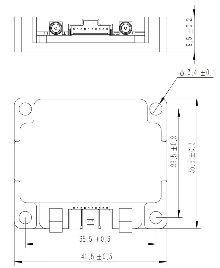
Mechanical Dimensions Diagram
Product Introduction
Product Overview
The MSU105 Mini Integrated Navigation System is a compact, cost-effective MEMS inertial navigation system designed for navigation, control, and measurement applications represented by SATCOM-on-the-move and UAVs. The system integrates MEMS sensors and a full-band GNSS receiver chip within a small form factor, enabling compact positioning and attitude measurement.
Product Features
- High performance, compact size, low weight
- Full-band GNSS support, high positioning and heading accuracy in complex environments
- Ultra-low steady-state power consumption of 0.5 W
- Full-temperature calibration and compensation from -45°C to 80°C
- Optional adaptive attitude and heading algorithm
- Online software upgrade capability, lever-arm error compensation
- Self-correction algorithm during GNSS outages to maintain horizontal attitude accuracy
- RTK differential support
Applications
- SATCOM-on-the-Move
- Position and attitude reference for UAVs, land vehicles, ships, and vessels
- Attitude Control
- UAVs and USVs
Technical Specifications
Table 1 MSU105 Mini Integrated Navigation System Performance Specifications
|
MEMS Gyroscope |
|
|
Range (°/s)° |
±300 |
|
Full-Temp. Bias (°/h)° |
≤360 |
|
Bias Stability (°/h, 10s avg.)° |
≤10 |
|
Bias Instability (°/h, Allan) |
≤3 |
|
Bias Repeatability (°/h)° |
≤10 |
|
Angular Random Walk (°/√h) |
≤0.3 |
|
Scale Factor Nonlinearity (ppm) |
≤100 |
|
Cross-Axis Coupling (rad) |
≤0.001 |
|
Bandwidth (Hz) |
≥100 |
|
MEMS Accelerometer |
|
|
Range (g) |
±16 |
|
Bias (mg) |
≤5 |
|
Bias Stability (µg, 10s avg.) |
≤300 |
|
Bias Stability (µg, Allan) |
≤50 |
|
Bias Repeatability (µg) |
≤300 |
|
Velocity Random Walk (mm/s/√h) |
≤50 |
|
Scale Factor Nonlinearity (ppm, ±1g) |
≤300 |
|
Cross-Axis Coupling (rad) |
≤0.001 |
|
Bandwidth (Hz) |
≥100 |
|
Integrated Navigation Accuracy |
|
|
Integrated Horizontal Position (m, 1σ) |
3 m (Single Point), 0.02+1 ppm (RTK) |
|
Integrated Vertical Position (m, 1σ) |
5 m (Single Point), 0.03+1 ppm (RTK) |
|
Integrated Horizontal Velocity (m/s, 1σ) |
0.1 |
|
Integrated Vertical Velocity (m/s, 1σ) |
0.15 |
|
Integrated Heading (°, 1σ, Real-Time) |
0.2 (1m Baseline Dual Antenna), 0.5 (Single Antenna, Dynamic) |
|
Integrated Horizontal Attitude (°, 1σ, Real-Time) |
0.1° (Dual Antenna), 0.2° (Single Antenna) |
|
Electrical/Mechanical Interface |
|
|
Power Supply (V) |
5 V (Ripple ≤ 100 mV) |
|
Steady-State Power (W) |
≤0.5 |
|
Startup Time (s) |
≤3 |
|
Communication Interface |
URAT |
|
Max Update Rate (Hz) |
100 |
|
Dimensions (mm×mm×mm) |
41.5×35.5×9.5 |
|
Weight (g) |
<30 |
|
Operating Environment |
|
|
Operating Temperature (°C) |
-40~+85 |
|
Storage Temperature (°C) |
-55~+85 |
|
Vibration (g, RMS) |
20~2000HZ,4.08 |
|
Shock (g) |
1000g/1ms |
|
Reliability |
|
|
MTBF(h) |
10000 |
Technical Specifications
Mechanical Characteristics
The mechanical interface of the MSU105 Mini Integrated Navigation System is shown in the figure below:
Dimensions: 41.5 mm × 35.5 mm × 9.5 mm (L × W × H, excluding connectors).
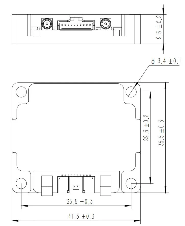
Figure 2 MSU105 Mini Integrated Navigation System Mechanical Interface Diagram
Product Marking and Polarity
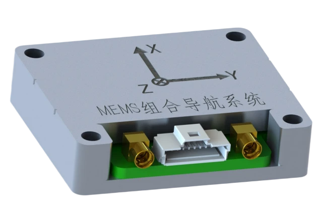
The product is placed horizontally with the arrow indicating the X direction. The output coordinate system is "Forward, Right, Down".
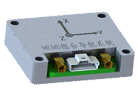
Figure 4 Vehicle Coordinate System Definition
Interface Definition
The external interface of the MSU105 Mini Integrated Navigation System is a Molex 501568-1007 receptacle, and the GNSS RF interface is a standard MMCX connector. The external interface definitions are listed in the following table:
Table 3 MSU105 Mini Integrated Navigation System Interface Cable Pin Definition
|
Pin |
Pin Definition |
Interface Definition |
Function Description |
|
1 |
Power Vin+ |
Input Range: 5 V |
Power Input |
|
2 |
Power GND |
GND |
Power Ground |
|
3 |
UART1_TX |
UART1 TX |
LVTTL Level |
|
4 |
UART1_RX |
UART1 RX |
LVTTL Level |
|
5 |
UART2_TX |
UART2 TX |
LVTTL Level |
|
6 |
UART2_RX |
UART2 RX |
LVTTL Level |
|
7 |
IMU_TX |
UART3 TX |
LVTTL Level |
|
8 |
IMU_RX |
UART3 RX |
LVTTL Level |
|
9 |
PPS_OUT |
PPS Signal Output |
LVTTL Level |
|
10 |
TOV_OUT |
IMU Acquisition Sync Output |
LVTTL Level |
After the supply voltage drops below the device operating threshold, the power-off hold time tOFF must be at least 3 s before re-powering; insufficient power-off interval may cause startup abnormalities, latch-up, or initialization failure.
External Communication
Protocol 1: Integrated Navigation Data Protocol
The MSU105 Mini Integrated Navigation System outputs data in a default timed broadcast mode at 200 Hz with a frame length of 164 bytes, a baud rate of 460800 bps, 1 start bit, 8 data bits, 1 stop bit, and no parity. Data transmission uses a little-endian (LSB first) format. The typical communication protocol is shown below, and it can also be customized according to user requirements.
Table 3 Integrated Navigation System Output Communication Protocol
|
No. |
Start Byte Offset |
Byte Length |
Signal Name |
Unit or Content |
Scaling |
Interface Precision Description |
|
1 |
0 |
1 |
Frame Header 1 |
Content: 55H |
1 |
8-bit unsigned integer |
|
2 |
1 |
1 |
Frame Header 2 |
Content: AAH |
1 |
8-bit unsigned integer |
|
3 |
2 |
1 |
Data Length |
Content: A0H |
1 |
8-bit unsigned integer |
|
4 |
3 |
4 |
PCNum |
Interrupt Counter |
1 |
32-bit unsigned integer |
|
5 |
7 |
1 |
System Status Word |
- |
1 |
Self-Test In Progress: 0x10; Self-Test OK: 0x12; Self-Test Error: 0x1F; Coarse Alignment: 0x33; Fine Alignment: 0x35; Pure Inertial Navigation: 0x41; Zero-Velocity Update: 0x43; Velocity + Position Integration: 0x44; Velocity + Position + Heading Integration: 0x45; Vehicle Constraint Navigation: 0x46; Odometer-Aided Navigation: 0x47; Self-Calibration in Progress: 0x51, 0x53, 0x55; Self-Calibration Completed, Criteria Valid: 0x56; Self-Calibration OK, Flash Write Successful: 0x57; Self-Calibration Error: 0x5F. |
|
6 |
8 |
1 |
Real-Time Status Word |
- |
1 |
|
|
7 |
9 |
2 |
Reserved Byte |
- |
1 |
|
|
8 |
11 |
4 |
Reserved Byte |
- |
1 |
|
|
9 |
15 |
4 |
X Gyro Angular Velocity |
[-1000,1000]°/s, |
0.0000005 |
Average within output cycle |
|
10 |
19 |
4 |
Y Gyro Angular Velocity |
[-1000,1000]°/s, |
0.0000005 |
Average within output cycle |
|
11 |
23 |
4 |
Z Gyro Angular Velocity |
[-1000,1000]°/s, |
0.0000005 |
Average within output cycle |
|
12 |
27 |
4 |
X Accelerometer Acceleration |
[-400m/s2,400m/s2] |
0.000001 |
Average within output cycle |
|
13 |
31 |
4 |
Y Accelerometer Acceleration |
[-400m/s2,400m/s2] |
0.000001 |
Average within output cycle |
|
14 |
35 |
4 |
Z Accelerometer Acceleration |
[-400m/s2,400m/s2] |
0.000001 |
Average within output cycle |
|
15 |
39 |
4 |
Integrated Longitude |
(-180,180]deg |
0.0000001 |
|
|
16 |
43 |
4 |
Integrated Latitude |
[-90,90]deg |
0.0000001 |
|
|
17 |
47 |
4 |
Integrated Altitude |
[-500,16384]m |
0.00001 |
|
|
18 |
51 |
2 |
Integrated North Velocity |
[-1310,1310]m/s |
0.005 |
|
|
19 |
53 |
2 |
Integrated Up Velocity |
[-1310,1310]m/s |
0.005 |
|
|
20 |
55 |
2 |
Integrated East Velocity |
[-1310,1310]m/s |
0.005 |
|
|
21 |
57 |
2 |
Roll Angle |
[-90,90]deg |
0.006 |
|
|
22 |
59 |
2 |
Heading Angle |
[-180,180]deg |
0.006 |
Positive north to west |
|
23 |
61 |
2 |
Pitch Angle |
[-85,85]deg |
0.006 |
|
|
24 |
63 |
4 |
GNSS Longitude |
(-180,180]deg |
0.0000001 |
|
|
25 |
67 |
4 |
GNSS Latitude |
[-90,90]deg |
0.0000001 |
|
|
26 |
71 |
4 |
GNSS Altitude |
[-500,16384]m |
0.00001 |
|
|
27 |
75 |
2 |
GNSS North Velocity |
[-1310,1310]m/s |
0.005 |
|
|
28 |
77 |
2 |
GNSS Up Velocity |
[-1310,1310]m/s |
0.005 |
|
|
29 |
79 |
2 |
GNSS East Velocity |
[-1310,1310]m/s |
0.005 |
|
|
30 |
81 |
1 |
Temperature |
[-127,127] |
1 |
|
|
31 |
82 |
1 |
Positioning and Heading Validity |
/ |
1 |
bits[3:0], Receiver Positioning Status: 00: No Fix; 01: Single Point Positioning; 02: Float Solution; 03: Fixed Solution; bits[7:4], Heading Signal: 00: No Heading; 01: Single Point Heading; 02: Float Heading; 03: Fixed Heading. |
|
32 |
83 |
4 |
GNSS Week Second Time |
|||
|
33 |
87 |
1 |
Year |
|||
|
34 |
88 |
1 |
Month |
|||
|
35 |
89 |
1 |
Day |
|||
|
36 |
90 |
1 |
Number of Satellites in Fix |
[0,255] |
1 |
|
|
37 |
91 |
2 |
GNSS Track Angle |
[-180,180]deg |
0.006 |
|
|
38 |
93 |
2 |
Dual-Antenna Heading |
[-180,180]deg |
0.006 |
|
|
39 |
95 |
2 |
Reserved |
|||
|
40 |
97 |
14 |
Reserved |
|||
|
41 |
111 |
12 |
Reserved |
|||
|
42 |
123 |
4 |
AU |
m/s2 |
1 |
Up Acceleration |
|
43 |
127 |
4 |
AF |
m/s2 |
1 |
Forward Acceleration |
|
44 |
131 |
4 |
AR |
m/s2 |
1 |
Right Acceleration |
|
45 |
135 |
4 |
heave |
m |
1 |
Relative Heave Displacement |
|
46 |
139 |
4 |
Filtered Output |
na |
1 |
|
|
47 |
143 |
4 |
Filtered Input |
na |
1 |
|
|
48 |
147 |
4 |
Primary Frequency |
na |
1 |
|
|
49 |
151 |
4 |
Data Time Integer Part |
- |
- |
|
|
50 |
155 |
4 |
Data Time Fractional Part |
- |
- |
|
|
51 |
159 |
4 |
Reserved |
- |
1 |
|
|
52 |
163 |
1 |
Checksum |
Lower 8 bits of the cumulative sum of data length and data bytes |
1 |
Precautions
- Strictly follow the pinout arrangement to avoid incorrect connections when using the product;
- This product is a precision measurement device. Avoid impacts, collisions, or other conditions beyond the product tolerance range during handling;
- The mounting of the product has a significant impact on angular velocity measurement. To avoid introducing installation errors, the mounting surface should be flat and level;
- To ensure measurement accuracy, the product must be mounted firmly and securely to avoid errors introduced by looseness;
- During installation and use, pay attention to ESD protection. Wearing an anti-static wrist strap is recommended;
- Follow this manual strictly during operation. Verify that the external environment matches the usage requirements. Do not disassemble the product, modify its internal structure, or perform unauthorized operations if issues arise. Please contact our technical personnel promptly for any questions.
Hot Tags: msu105 mini mems integrated inertial navigation system, China msu105 mini mems integrated inertial navigation system manufacturers, factory