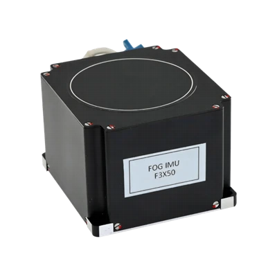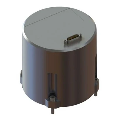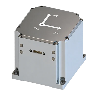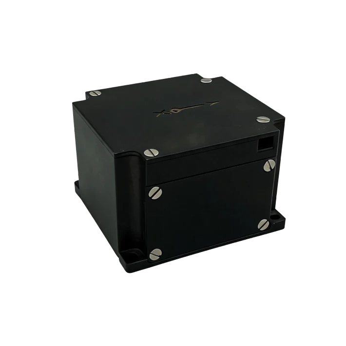
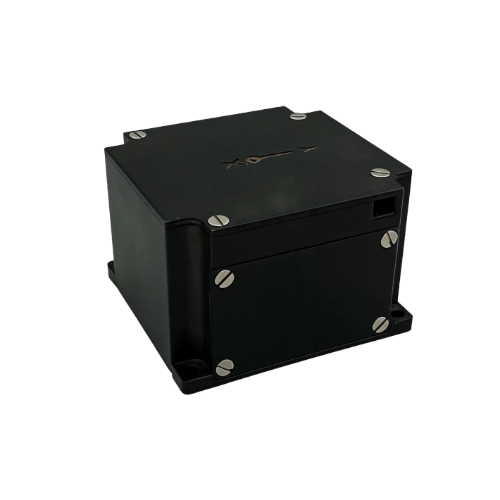
F3X70 Three-Axis FOG IMU
Robust environmental adaptability
High reliability, ultra-long lifetime
Full digital RS-422 electrical interface
Description
Key Features
- Compact micro design
- All-solid-state design
- Robust environmental adaptability
- High reliability, ultra-long lifetime
- Full digital RS-422 electrical interface
Applications
- Mobile survey & attitude
- Unmanned systems (ground/marine/UW)
- Surveying & north-finding
- Stabilized platforms
- SATCOM-on-the-move
- Autonomous driving & munitions
Product Introduction
Company's F3X70 is a three-axis FOG IMU purpose-built for the navigation, guidance, and attitude control systems of small missiles and guided bombs. Comprising three all-solid-state FOGs, three quartz accelerometers, and a data packaging board, it measures angular velocity and linear acceleration to support attitude and navigation control. Its all-solid-state architecture eliminates moving parts for excellent shock and vibration resistance, and RS-422 serial output enables seamless system integration in high-dynamic precision guidance and attitude measurement applications.
Unique Technology
Company is a high-tech enterprise with full closed-loop capabilities from fiber winding equipment and coils to FOGs, fiber/MEMS inertial products, IMU circuits, software, and test equipment. End-to-end process control improves quality and reduces costs. Operating under ISO9001 with strict processes, it ensures product reliability and consistency.
F3X70 Three-Axis Fiber Optical Gyro IMU Performance Specifications
|
Parameter |
A |
B |
C |
||||
|
Fiber Optic Gyroscope |
|||||||
|
RT Bias Repeatability (run-to-run, day-to-day) (°/h) |
≤0.5 |
≤0.3 |
≤0.20 |
||||
|
Constant-Temp Bias Stability (°/h) |
≤0.5 |
≤0.3 |
≤0.20 |
||||
|
RT SF Repeatability (ppm) |
≤50 |
≤30 |
≤20 |
||||
|
Constant-Temp SF Asymmetry (ppm) |
≤30 |
≤20 |
≤20 |
||||
|
Constant-Temp SF Nonlinearity (ppm) |
≤30 |
≤20 |
≤20 |
||||
|
Threshold (°/h) |
≤0.5 |
||||||
|
Angular Rate Range (°/s) |
±1000 |
||||||
|
Bandwidth (Hz) |
200 |
||||||
|
Dimensions (mm) |
70*70*45 |
||||||
|
Weight (g) |
400±50 |
||||||
|
Operating Temperature (°C) |
-40~+65 |
||||||
|
Quartz Accelerometer |
|||||||
|
Specifications |
Min. |
Typ. |
Max. |
Unit |
|||
|
Measurement Range |
-20 |
- |
+20 |
g |
|||
|
Bias Instability |
- |
30 |
- |
μg |
|||
|
Velocity Random Walk |
- |
0.02 |
- |
m/s/√h |
|||
|
Resolution |
- |
0.02 |
- |
mg |
|||
|
Nonlinearity Accuracy |
- |
0.1 |
- |
%FS |
|||
|
Bandwidth |
- |
200 |
- |
Hz |
|||
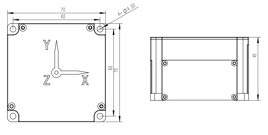
Mechanical Dimensions Diagram
Introduction
This fiber optic IMU is an inertial product developed for navigation, guidance, attitude measurement, and control systems of small missiles and guided bombs. It consists of three all-solid-state FOGs, three quartz accelerometers, and a data packaging board, measuring angular velocity and linear acceleration to provide attitude and navigation control information. Measurement results are output via RS-422 serial interface.
1.1 Scope of Application
This manual applies only to the F3X70 product and includes performance specifications, technical conditions, dimensions, and installation/usage. Technical conditions cover environmental range, electrical performance, and physical characteristics.
1.2 Main Specifications
1.2.1 FOG Main Performance Specifications:
|
Fiber OpticGyroscopeMainPerformanceSpecifications |
Parameter |
A |
B |
C |
|
RT Bias Repeat. (run-to-run, day-to-day) ( º/ h) |
≤0.5 |
≤0.3 |
≤0.20 |
|
|
Const-Temp Bias Stability ( º/ h) |
≤0.5 |
≤0.3 |
≤0.20 |
|
|
RT SF Repeatability ( ppm) |
≤50 |
≤30 |
≤20 |
|
|
Const-Temp SF Asymmetry ( ppm) |
≤30 |
≤20 |
≤20 |
|
|
Const-Temp SF Nonlinearity ( ppm) |
≤30 |
≤20 |
≤20 |
|
|
Threshold ( º/ h) |
≤0.5º/ h |
|||
|
Angular Rate Range( º/s) |
±1000 |
|||
|
Bandwidth ( Hz) |
200 |
|||
|
Dimensions ( mm) |
70*70*45 |
|||
|
Weight (g) |
400±50 |
|||
|
Operating Temp. (°C) |
-40~+65 |
|||
Table 1 Product Main Performance Specifications
|
Parameter |
Min. |
Typ. |
Max. |
Unit |
|
|
Accelerometer Specifications |
Range |
-20 |
+20 |
g |
|
|
Bias Instability |
30 |
μg |
|||
|
Velocity Random Walk |
0.02 |
m/s/√h |
|||
|
Resolution |
0.02 |
mg |
|||
|
Nonlinearity Accuracy |
0.1 |
%FS |
|||
|
Bandwidth |
200 |
Hz |
|||
1.2.2 Mechanical Testing
1.2.2.1 Sine Sweep Vibration
Mount the gyro on the vibration table by axis direction using fixtures. Perform sine sweep in three directions: X, Y, and Z axes. Procedure: energize vibration table, power on gyro, warm up for a period (gyro start-up time), measure gyro output for approx. 5 min, then apply sine vibration. Conditions: 20 Hz-2000 Hz, sweep time 5 min, amplitude 4.2 g. Record gyro output during vibration.
Random Vibration
Frequency: 20 Hz-2000 Hz
Duration: 5 min per axis
Direction: X, Y, Z axes
Spectrum: See Attachment 1 ttachment 1: Vibration Spectrum
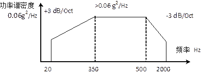
Requirements:
FOG exhibits no resonance during sine sweep from 20 Hz to 2000 Hz;
Random vibration: absolute difference between in-vibration bias and pre/post average bias shall be <0.3°/h.
1.2.2.2 Mechanical shock per Table 2.
Table 2 Shock Test Conditions
|
Peak Acceleration (g) |
30 |
|
Duration (ms) |
10 |
|
Shock Count |
per direction3times |
|
Waveform |
Half-sine |
|
Direction |
X,Y,Z |
|
Note: Interval between shocks ≥1.5s |
The product shall remain powered during shock testing and function normally afterward. Bias change before/after shock shall be <0.3°/h.
Appendix A:
Baud rate: 460800, no parity, 1 stop bit
Output frequency: 400 Hz
Output data protocol:
|
Byte |
Name |
Unit |
Value |
Conversion |
Type |
|
0 |
Frame Header1 |
0xAA |
uchar |
||
|
1 |
Frame Header2 |
0xAA |
uchar |
||
|
2 |
Tx Counter |
1~200 |
uchar |
||
|
3 |
Self-test Byte |
255 |
uchar |
||
|
4~7 |
XAxis Gyro |
32bitLSB first |
signed int32 |
||
|
8~11 |
YAxis Gyro |
32bitLSB first |
signed int32 |
||
|
12~15 |
ZAxis Gyro |
32bitLSB first |
signed int32 |
||
|
16~19 |
XAxis Accel |
32bitLSB first |
signed int32 |
||
|
20~23 |
YAxis Accel |
32bitLSB first |
signed int32 |
||
|
24~27 |
ZAxis Accel |
32bitLSB first |
signed int32 |
||
|
28,29 |
XAxis Gyro Temp |
16bitLSB first |
1/16 |
signed int16 |
|
|
30 |
Checksum |
4~29 Byte XOR sum |
uchar |
||
|
31 |
Frame Tail |
0xBB |
uchar |
3. Wiring Definition
The FOG uses a J30-15ZKP receptacle. Pinout defined in Table 1.
Table 1 FOG Output Connector Electrical Characteristics
|
Pin |
Definition |
Label |
Color |
|
1 |
TXD+ |
TX+ |
Yellow |
|
2 |
TXD- |
TX- |
Orange |
|
3 |
RXD+ |
RX+ |
Blue |
|
4 |
RXD- |
RX- |
Green |
|
5, 13 |
+5 V Power |
+5V |
Red |
|
6, 7 |
GND |
GND |
Black |
Product Dimensions
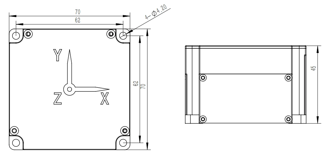
F3X70 Dimensional Drawing
Hot Tags: f3x70 three-axis fog imu, China f3x70 three-axis fog imu manufacturers, factory