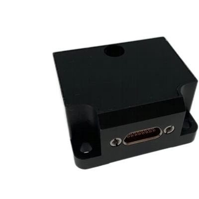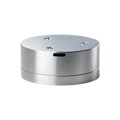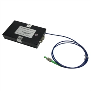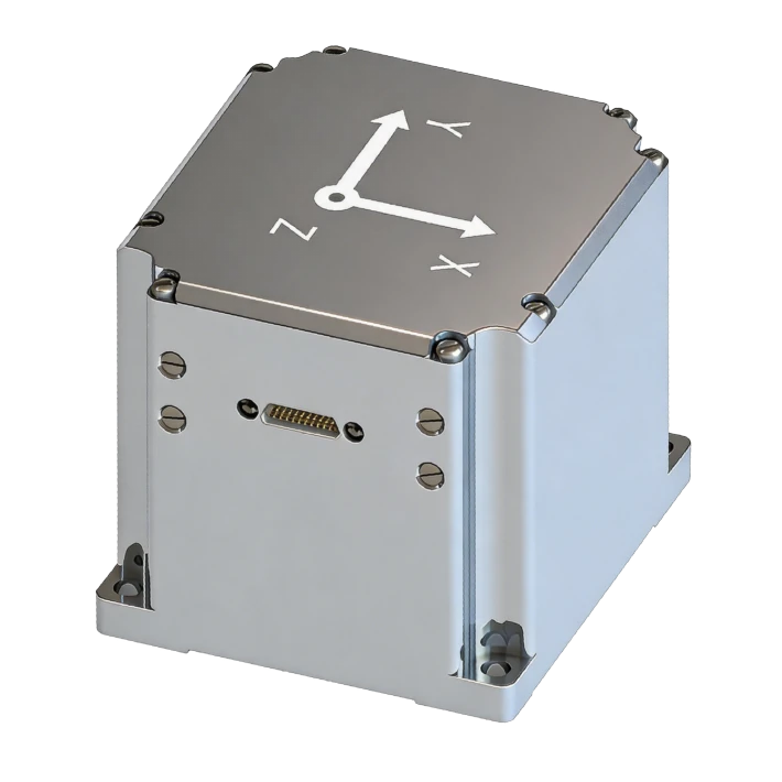
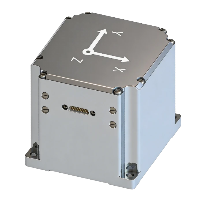
FSU305 Fiber Inertial Navigation System
Rich I/O
Low power 10 W
Full-temp calibration
Harsh-environment resistant
Description
Key Features
- Lightweight, domestic
- Full-band GNSS, high precision
- Rich I/O
- Low power 10 W
- Full-temp calibration
- Harsh-environment resistant
- Vibration & EMI resistant
- Online upgrade, self-calib
- Pure inertial accuracy
- RTK differential
- ZUPT for vehicle
Applications
- Mobile survey & attitude
- Unmanned systems (ground/marine/UW)
- Surveying & north-finding
- Stabilized platforms
- SATCOM-on-the-move
- Autonomous driving & munitions
Product Introduction
Company FSU305 is a high-reliability, cost-effective fiber optic inertial navigation system for aircraft, UGVs, USVs, UAVs, and similar platforms. Its modular design combines silicon photonic gyroscopes and FM accelerometers with multi-sensor fusion, filtering combined INS and GPS data and correcting errors to output high-precision position, velocity, and attitude. Supporting airborne, vehicular (vehicle constraints extend precision hold time), and marine configurations, its software is configurable for transfer alignment, integrated navigation, and pure INS modes.
Unique Technology
Company is a high-tech enterprise with full closed-loop capabilities from fiber winding equipment and coils to FOGs, fiber/MEMS inertial products, IMU circuits, software, and test equipment. End-to-end process control improves quality and reduces costs. Operating under ISO9001 with strict processes, it ensures product reliability and consistency.
FSU305 Fiber Inertial Navigation System Performance Specifications
|
Parameter |
Specifications |
|
Fiber OpticGyroscope |
|
|
Range (°/s) |
±500 |
|
Bias (°/h) |
≤1 |
|
Bias Stability (°/h, 10s avg.) |
≤0.5 |
|
Bias Instability (°/h, Allan, typ.) |
≤0.05 |
|
Bias Repeatability (°/h, 6 power-on cycles) |
≤0.5 |
|
Angular Random Walk (°/√h) |
≤0.05 |
|
Scale Factor Nonlinearity (ppm) |
≤200 |
|
Cross-Coupling (rad) |
≤0.001 |
|
Bandwidth (Hz) |
≥200 |
|
FMAccelerometer |
|
|
Range (g) |
±30 |
|
Full-Temperature Bias (mg, 3σ) |
≤0.5 |
|
Bias Stability (μg, 10s avg.) |
≤10 |
|
Bias Instability (μg, Allan, typ.) |
≤3 |
|
Bias Repeatability (μg) |
≤10 |
|
Velocity Random Walk (m/s/√h) |
≤0.01 |
|
Scale Factor Nonlinearity (ppm, ±1g) |
≤100 |
|
Cross-Coupling (rad) |
≤0.001 |
|
Bandwidth (Hz) |
≥200Hz |
|
Integrated Navigation Accuracy |
|
|
Integrated Heading Accuracy (°, 1σ, real-time) |
0.5 |
|
Integrated Horizontal Attitude (°, 1σ, real-time) |
0.06 |
|
Integrated Heading Accuracy (°, post-processed) |
0.06 |
|
Integrated Horizontal Attitude (°, post-processed) |
0.01 |
|
Integrated Horizontal Position (m, 1σ) |
3 (standalone), 0.02 + 1 ppm (RTK) |
|
Integrated Vertical Position (m, 1σ) |
5 (standalone), 0.03 + 1 ppm (RTK) |
|
Integrated Horizontal Velocity (m/s, 1σ) |
0.1 |
|
Integrated Vertical Velocity (m/s, 1σ) |
0.15 |
|
Parameter |
Specifications |
|
GNSS Receiver (External) |
|
|
Timing Accuracy |
20ns |
|
Cold Start TTFF |
≤40s |
|
Start-Up Time |
≤2s |
|
Position Update Rate |
10Hz |
|
Operating Altitude |
10000m |
|
Satellite Modes |
GPS: L1/L2/L5; BeiDou: B1/B2/B3; GLONASS: L1/L2. |
|
Electrical/Mechanical Interface |
|
|
Power Supply (V) |
12~36VDC(recommended24V) |
|
Steady-State Power(W) |
≤10W |
|
Start-Up Time (s) |
3 |
|
Communication Interface |
RS-422 |
|
Update Rate (Hz,max) |
1000(IMU) ,200(INS) |
|
Dimensions (mm×mm×mm) |
65×70×63 |
|
Weight (g) |
≤500 |
|
Operating Environment |
|
|
Operating Temperature |
-40~70 |
|
Storage Temperature |
-55~85 |
|
Vibration |
20~2000HZ,6.06 |
|
Shock |
100/1ms |
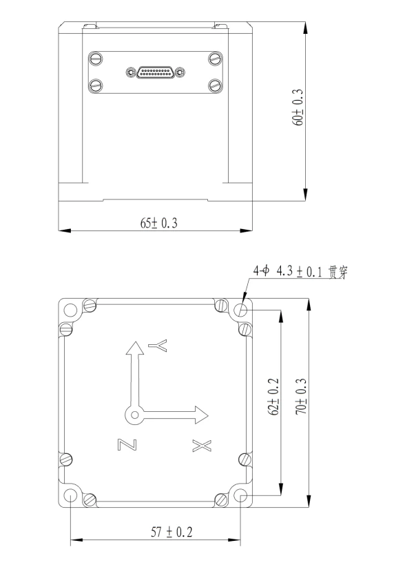
Mechanical Dimensions Diagram
Device Description
Product Overview
FSU305 fiber inertial navigation system is a high-reliability, cost-effective navigation system widely used in navigation, control, and measurement for aircraft, UGVs, USVs, and UAVs.
The INS inherits modular product design, employing high-precision silicon photonic gyroscopes and high-precision FM accelerometers. Through multi-sensor fusion, the primary INS, GPS position, and velocity enter a Kalman filter alongside INS outputs; the filter compares differences, builds error models, and corrects INS results for integrated velocity, position, and attitude. The INS supports configurable modes for airborne, vehicle, and marine platforms; land vehicles include vehicle constraint,through error estimation and correction, achieving long-duration high-precision navigation and positioning.
The FSU305 series integrated navigation system supports flexible software configuration based on user requirements, including transfer alignment, integrated navigation, pure INS computation, and AHRS modes to maximize compatibility with diverse applications.
Product Composition
The FSU305 fiber SINS consists of a three-axis silicon photonic gyroscope, high-precision FM accelerometer, signal processing circuit, navigation software, mechanical components, test cable, receiver board (optional), GNSS antenna (optional), and feed line (optional). Key components include:
Table 1 INS Main Components
|
No. |
Composition Component |
Qty |
Model |
Remarks |
|
1 |
High-Precision INS |
1 |
FSU305 |
|
|
2 |
Connector Plug |
1 |
J20JD-21TJL |
Male |
|
3 |
Receiver Board |
1 |
Optional |
|
|
4 |
GNSS Antenna |
2 |
BT-800S |
Optional Magnetic or screw mount |
|
5 |
GNSS Antenna Cable |
2 |
TNC Male-SMA Male |
Optional 5m |
Key Features
- Key features of the FSU305 fiber SINS are as follows:
- Domestic core components, high performance, modular, lightweight
- Full-band GNSS, high positioning/orientation accuracy in complex environments
- Rich interfaces
- 10 W steady-state power consumption
- Full-temperature calibration, -40°C to +70°C
- Mechanical environment resistant
- Vibration, shock, and EMI resistant
- Online firmware upgrade and installation error compensation
- Self-correction algorithm during GNSS outages, maintaining horizontal accuracy
- RTK differential support
- ZUPT and vehicle constraint algorithms for improved autonomous accuracy
Applications
Primary application areas of the FSU305 fiber SINS:
- Mobile position and attitude measurement
- UGVs, USVs/UUVs
- Surveying
- Stabilized platforms
- Underwater vehicles
- SATCOM on the move
- Intelligent driving
- Munition guidance
- Intelligent mining north-finding
Technical Parameters
System Specifications
Table 2 FSU305 Fiber SINS Performance Specifications
|
Silicon Photonic Gyro |
|
|
Range (°/s) |
±500 |
|
Bias (°/h) |
≤1 |
|
Bias Stability (°/h, 10s avg.) |
≤0.5 |
|
Bias Instability (°/h, Allan, typ.) |
≤0.05 |
|
Bias Repeatability (°/h, 6 cycles) |
≤0.5 |
|
Angular Random Walk (°/√h) |
≤0.05 |
|
Scale Factor Nonlinearity (ppm) |
≤200 |
|
Cross-Coupling (rad) |
≤0.001 |
|
Bandwidth (Hz) |
≥200 |
|
FM Accelerometer |
|
|
Range (g) |
±30 |
|
Full-Temperature Bias (mg,3σ) |
≤0.5 |
|
Bias Stability (μg,10savg.) |
≤10 |
|
Bias Instability (μg,allan,typ) |
≤3 |
|
Bias Repeatability (ug) |
≤10 |
|
Velocity Random Walk (m/s/√h) |
≤0.01 |
|
Scale Factor Nonlinearity (ppm,±1g) |
≤100 |
|
Cross-Coupling (rad) |
≤0.001 |
|
Bandwidth (Hz) |
≥200Hz |
|
Integrated Nav Accuracy |
|
|
Integrated Heading Accuracy (°, 1σ, real-time) |
0.5 |
|
Integrated Horizontal Attitude (°, 1σ, real-time) |
0.06 |
|
Integrated Heading Accuracy (°, post-proc) |
0.06 |
|
Integrated Horizontal Attitude (°, post-proc) |
0.01 |
|
Integrated HorizontalPosition (m, 1σ) |
3 (standalone),0.02+1ppm (RTK) |
|
Integrated VerticalPosition (m, 1σ) |
5 (standalone), 0.03+1ppm (RTK) |
|
Integrated Horizontal Velocity (m/s, 1σ) |
0.1 |
|
Integrated Vertical Velocity (m/s, 1σ)) |
0.15 |
|
GNSS Receiver (External) |
|
|
TimingAccuracy |
20ns |
|
Cold Start TTFF |
≤40s |
|
Start-UpTime |
≤2s |
|
Position Update Rate |
10Hz |
|
Operating Altitude |
10000m |
|
Satellite Modes |
GPS: L1/L2/L5; BeiDou: B1/B2/B3; GLONASS: L1/L2. |
|
Electrical/Mech. Interface |
|
|
Power Source (V) |
12~36VDC(recommended24V) |
|
Steady-State Power(W) |
≤10W |
|
Start-Up Time (s) |
3 |
|
Comm. Interface |
RS-422 |
|
Update Rate (Hz,max) |
1000(IMU) ,200(INS) |
|
Dimensions (mm×mm×mm) |
65×70×63 |
|
Weight (g) |
≤500 |
|
Operating Environment |
|
|
Operating Temperature |
-40~70 |
|
Storage Temperature |
-55~85 |
|
Vibration |
20~2000HZ,6.06 |
|
Shock |
100/1ms |
Mechanical Interface
Mechanical interface of the FSU305 fiber SINS is shown in the figure below:
INS weight (excluding GNSS antenna and feed line): ≤500 g;
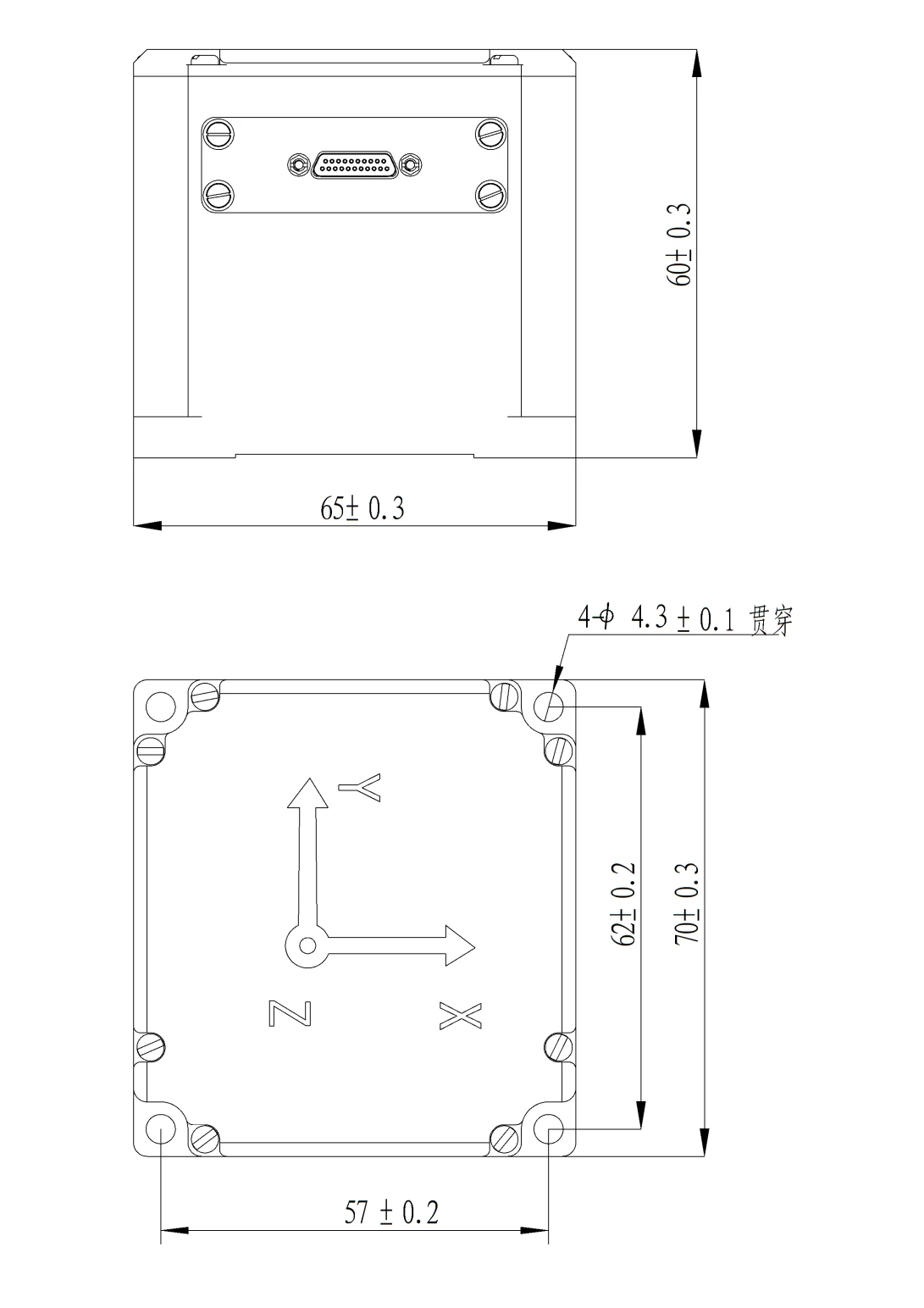
Fig. 2 FSU305 Fiber Strapdown Inertial Navigation System Mechanical Interface Fig.
GNSS antenna standard dimensions: 65 × 70 × 63 mm, base secured with 4 M4 screws.
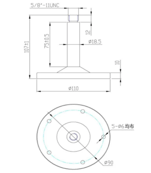
Fig. 3 FSU305 Fiber Strapdown Inertial Navigation System GNSS Antenna Mechanical Interface
GNSS antenna also available with magnetic base: 100 × 100 × 66 mm.
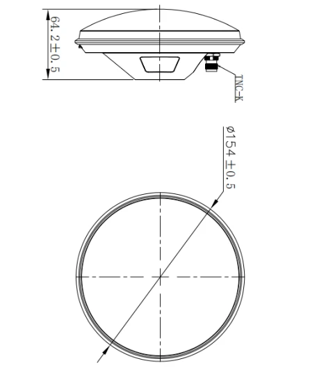
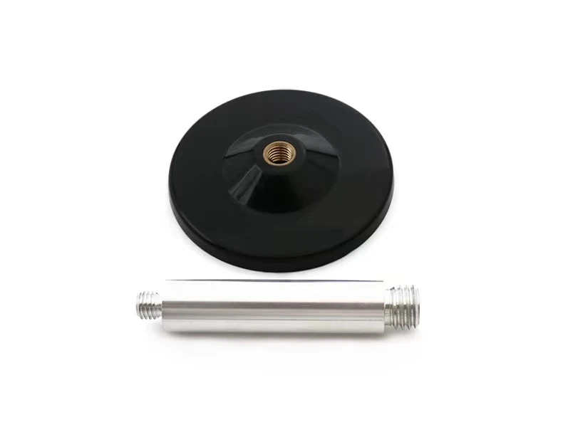
Fig. 4 FSU305Fiber SINSGNSS Antenna Magnetic Base
Electrical Interface
The FSU305 SINS uses a J20JD-21ZKP electrical connector, mating with J20JD-21TJL plug. The connector pinout is defined as follows:
Table 3 FSU305 Fiber SINS Connector Pinout
|
Pin No. |
Definition |
External DB9 |
Type |
Remarks |
|
+VIN |
External 24 V Power |
Power Source |
Red alligator clip |
|
|
GND |
Power Source |
Black alligator clip |
||
|
COM1_Rx+ |
External RS422 non-isolated port 1 |
Receive from aircraft INS |
DB9-M1-1 |
|
|
COM1_Rx- |
DB9-M1-2 |
|||
|
COM1_Tx+ |
Transmit integrated nav data |
DB9-M1-3 |
||
|
COM1_Tx- |
DB9-M1-4 |
|||
|
GND |
DB9-M1-5 |
|||
|
COM2_Tx+ |
External RS422 non-isolated2 |
Transmit raw IMU data |
DB9-M2-3 |
|
|
COM2_Tx- |
DB9-M2-4 |
|||
|
GND |
DB9-M2-5 |
|||
|
COM2_PPS_IN+ |
PPS differential input, non-isolated |
Composite pulse input |
DB9-M3-1 |
|
|
COM2_PPS_IN- |
DB9-M3-2 |
|||
|
COM3_PPS_OUT+ |
PPS differential output, non-isolated |
Differential PPS output |
DB9-M3-3 |
|
|
COM3_PPS_OUT- |
DB9-M3-4 |
|||
|
GND |
DB9-M3-5 |
|||
|
COM3_Rx+ |
External RS422 non-isolated 4 |
Receive GPS from receiver board |
DB9-M4-1 |
|
|
COM3_Rx- |
DB9-M4-2 |
|||
|
GND |
DB9-M4-5 |
|||
|
RS232_TXD1 |
External RS232 non-isolated 1 |
DebugPort, firmware upgrade |
DB9-M5-2 |
|
|
RS232_RXD1 |
DB9-M5-3 |
|||
|
GND |
DB9-M5-5 |
Data Protocol and Analysis
Protocol 1: Host-to-INS Command
After self-check passes, the INS accepts valid user commands and executes corresponding functions per the protocol, as detailed below.
Table 4 FSU305 Fiber SINS Host-to-INS Protocol
|
Content |
Source |
EO Pod |
||
|
Target |
IMU (with nav board) |
|||
|
Interval |
Frame Rate200 Hz |
|||
|
Baud Rate |
460800bps |
|||
|
No. |
Sign |
Byte Count |
Content |
Data Definition |
|
1 |
Head1 |
1 |
Header 1 |
0xEB |
|
2 |
Head2 |
2 |
Header 2 |
0x90 |
|
3 |
|
3~4 |
Reserved |
|
|
4 |
ωYaw |
5~6 |
Master INSZ Angular Rate |
Int16, resolution 300/215 Unit:°/sdown, right turn positive. |
|
5 |
ωPitch |
7~8 |
Master INS X Angular Rate |
Int16, resolution 300/215 Unit:°/sright, nose-up positive. |
|
6 |
ωRoll |
9~10 |
Master INS Y Angular Rate |
Int16, resolution 300/215 Unit:°/sforward, right roll positive. |
|
7 |
Stars |
11 |
Satellites |
|
|
8 |
PDOP |
12 |
Nav Accuracy Factor |
1-100 |
|
9 |
IMU |
13 |
Master INS Status |
0x11, integrated nav data valid; 0x22, pure INS data valid; 0x33, nav data invalid; 0x44, alignment data; Note:0x11,0x22 = INS valid;0x33,0x44 = INS invalid. All info. |
|
10 |
Yaw |
14~15 |
INS Heading |
LSB first 16 -bit unsigned integer 0~359.99º LSB = 0.01º(North-referenced, 0, positive east is 90º) |
|
11 |
Pitch |
16~17 |
Master INS Pitch |
LSB first 16 -bit signed integer -89.99 º~+89.99º LSB = 0.01º(nose-up positive) |
|
12 |
Roll |
18~19 |
INS Roll |
LSB first 16 -bit signed integer -179.99 º~+179.99 º LSB = 0.01º(right roll positive) |
|
13 |
Lon |
20~23 |
Master INS Longitude |
LSB =0.001",East longitude positive, LSB first 32 -bit signed integer Note: Resolution unit is arc-seconds. |
|
14 |
Lat |
24~27 |
Master INS Latitude |
LSB =0.001",North latitude positive, LSB first 32 -bit signed integer Note: Resolution unit is arc-seconds. |
|
15 |
ALt1 |
28~29 |
Master INS Altitude |
LSB =1m, LSB first 16 -bit signed integer,-300m--10000m |
|
16 |
|
30~31 |
Reserved |
|
|
17 |
Hdg |
32~33 |
Master INS Ground Speed Direction |
LSB =0.01°,0°~359.99° (N-biased E positive) LSB first MSB,16 -bit unsigned integer |
|
18 |
Vg |
34~35 |
Master INS Ground Speed |
LSB =0.01m/s, LSB first,16 -bit unsigned count,0--650m/s |
|
19 |
Vu |
36~37 |
Master INS Up Velocity |
(up positive),16 -bit signed integer,-200m/s --200m/s, LSB=200m/s/215 , |
|
20 |
GPS relative Position X |
38 |
Master INS relative to pod X Position |
8 -bit signed,-128~127 Table-12.8~12.7 m, resolution 0.1 m. EOPod-centered, pod-to-INS, aircraft right X Forward Y Up Z coordinate system. |
|
21 |
GPS relative Position Y |
39 |
Master INS relative to pod Y Position |
|
|
22 |
GPS relative Position Z |
40 |
Master INS relative to pod Z Position |
|
|
23 |
Alt2 |
41~42 |
Pressure Altitude |
16 -bit signed, LSB first Range:-300m~10000m LSB=1m(unused) |
|
24 |
Ve |
43~44 |
Master INS East Velocity |
-200m/s --200m/s,LSB=200m/s/(215-1) , |
|
25 |
Vn |
45~46 |
Master INS North Velocity |
-200m/s --200m/s,LSB=200m/s/(215-1), |
|
26 |
Status2 |
47 |
BeiDou Status |
UTC Time Valid Flag. 0x55: Position fix; 0xAA: No fix. |
|
27 |
GPSUTC |
48~51 |
UTC Time |
, GPS data-synchronized GPSUTC Time, ms |
|
28 |
Command |
52 |
Command |
0x5A: Static Alignment 0x5B: Dynamic Alignment 0xAB: Realign (any time) 0x6A: Start Calib Default:00 |
|
29 |
azimpod
|
53~54 |
Azimuth Frame Angle |
16 -bit unsigned, LSB first Range 0~36000 Table 0°~+360°,right positive, resolution = 0.01°. |
|
30 |
pitchpod |
55~56 |
Pitch Frame Angle |
16 -bit signed, LSB first Range-18000~+18000 Table-180°~+180°, upward positive, resolution 0.01°. |
|
31 |
Flag |
57 |
INS Update Flag |
0: Not updated 1: Updated |
|
32 |
Flag |
58 |
Frame Angle Update Flag |
0: Not updated 1: Updated |
|
33 |
Checksum |
59 |
Checksum |
1 -58 byte sum, lower 8 bit |
|
34 |
Frame Tail |
60 |
|
0x5A |
Protocol 2: Integrated Navigation Data
The FSU305 fiber SINS outputs data in timed broadcast mode at 200 Hz, 164 bytes per frame, 460800 bps baud rate, 1 start bit, 8 data bits, 1 stop bit, no parity. Multi-byte variables: LSB first. The typical protocol is shown below; protocols can be customized per user requirements.
Table 5 FSU305 Fiber SINS Output Protocol
|
No. |
Byte Offset |
Byte Count |
Signal Name |
Unit / Content |
Scale |
Accuracy |
|
1 |
0 |
1 |
Header1 |
Content:55H |
1 |
8-bit unsigned integer |
|
2 |
1 |
1 |
Header2 |
Content:AAH |
1 |
8-bit unsigned integer |
|
3 |
2 |
1 |
Data Length |
Content:A0H |
1 |
8-bit unsigned integer |
|
4 |
3 |
4 |
PCNum |
Interrupt Counter |
1 |
32-bit unsigned integer |
|
5 |
7 |
1 |
System Status |
na |
1 |
Self-test: 0x10, Vel+Pos: 0x44, Vel+Pos+Heading: 0x45; |
|
6 |
8 |
1 |
Real-Time Status |
na |
1 |
See Real-Time Status definition |
|
7 |
9 |
2 |
Operating Status |
na |
1 |
See Device Status definition |
|
8 |
11 |
4 |
Process Status |
na |
1 |
See Process Status definition |
|
9 |
15 |
4 |
GX1 |
[-1000,1000]°/s, |
0.0000005 |
Right, output periodAverage |
|
10 |
19 |
4 |
GY1 |
[-1000,1000]°/s, |
0.0000005 |
Forward, output periodAverage |
|
11 |
23 |
4 |
GZ1 |
[-1000,1000]°/s, |
0.0000005 |
Upward, output periodAverage |
|
12 |
27 |
4 |
AX1 |
[-400,400]m/s2 |
0.000001 |
Right, output periodAverage |
|
13 |
31 |
4 |
AY1 |
[-400,400]m/s2 |
0.000001 |
Forward, output periodAverage |
|
14 |
35 |
4 |
AZ1 |
[-400,400]m/s2 |
0.000001 |
Upward, output periodAverage |
|
15 |
39 |
4 |
IntegratedLongitude |
(-180,180]deg |
0.0000001 |
User Target Position |
|
16 |
43 |
4 |
IntegratedLatitude |
[-90,90]deg |
0.0000001 |
|
|
17 |
47 |
4 |
IntegratedAltitude |
m |
0.00001 |
|
|
18 |
51 |
2 |
Integrated North Vel |
[-163.84,163.84]m/s |
0.005 |
coarse alignment, outputflashinternalXGyro Bias, North |
|
19 |
53 |
2 |
Integrated Up Vel |
[-163.84,163.84]m/s |
0.005 |
coarse alignment, outputflashinternalYGyro Bias, Up |
|
20 |
55 |
2 |
Integrated East Vel |
[-163.84,163.84]m/s |
0.005 |
coarse alignment, outputflashinternalZGyro Bias, East |
|
21 |
57 |
2 |
Roll Angle |
[-180,180]deg |
0.006 |
|
|
22 |
59 |
2 |
Heading |
[0,360]deg |
0.006 |
N-biasEastpositive. |
|
23 |
61 |
2 |
Pitch |
[-85,85]deg |
0.006 |
|
|
24 |
63 |
4 |
Master INSLongitude/GNSSLogi |
(-180,180]deg |
0.0000001 |
|
|
25 |
67 |
4 |
Master INSLatitude |
[-90,90]deg |
0.0000001 |
|
|
26 |
71 |
4 |
Master INSAltitude |
m |
0.00001 |
|
|
27 |
75 |
2 |
INS North Vel |
[-163.84,163.84]m/s |
0.005 |
coarse alignment, outputflashinternalXAccel Bias, North |
|
28 |
77 |
2 |
INS Up Vel |
[-163.84,163.84]m/s |
0.005 |
coarse alignment, outputflashinternalYAccel Bias, Up |
|
29 |
79 |
2 |
INS East Vel |
[-163.84,163.84]m/s |
0.005 |
coarse alignment, outputflashinternalZAccel Bias, East |
|
30 |
81 |
1 |
Tg |
[-127,127]℃ |
1 |
|
|
31 |
82 |
1 |
AnchorFlag |
na |
1 |
bit0-3, RX Fix Flag: |
|
32 |
83 |
4 |
uiMSow |
s |
0.001 |
UTC time converted to GPSTOW, no leap second |
|
33 |
87 |
1 |
Master INS Status |
1 |
0x11, integrated nav data valid; |
|
|
34 |
88 |
1 |
Master INSCommand |
1 |
0x5A: Static Align |
|
|
35 |
89 |
1 |
FRMID |
1 |
0xF1 |
|
|
36 |
90 |
1 |
Satellites |
na |
1 |
|
|
37 |
91 |
2 |
INS Roll Angle |
[-180,180]deg, track angle |
0.006 |
Roll before nav; |
|
38 |
93 |
2 |
MINSHeading |
[0,360]deg, INS Heading |
0.006 |
E-positive from N. |
|
39 |
95 |
2 |
Reserved |
1 |
||
|
40 |
97 |
2 |
Master INS Pitch |
[-90,90]deg, Master INS |
0.006 |
|
|
41 |
99 |
2 |
Pressure Alt |
0.5 |
Raw Pressure Alt |
|
|
42 |
101 |
2 |
RTCheckSta16 |
1 |
||
|
43 |
103 |
2 |
Reserved |
deg |
0.006 |
|
|
44 |
105 |
2 |
MContiValidCnt |
na |
1 |
|
|
45 |
107 |
1 |
RIERRCode |
na |
1 |
GNSS Error Code |
|
46 |
108 |
1 |
RIValidCnt |
na |
1 |
Receiver Valid Count |
|
47 |
109 |
1 |
ErrRIZKCnt |
na |
1 |
ZkRIcount |
|
48 |
110 |
1 |
Calibration Process |
na |
1 |
|
|
49 |
111 |
1 |
GPS_KFcnt |
na |
1 |
GNSS Filter Update Counter |
|
50 |
112 |
1 |
MSyncHdFlag |
na |
1 |
INS Heading Sync Flag |
|
51 |
113 |
1 |
RTCheckStaH8 |
na |
1 |
Heading Filter Update Count |
|
52 |
114 |
1 |
HdCorCnt |
na |
1 |
Heading Correction Count |
|
53 |
115 |
1 |
AttCorCnt |
na |
1 |
Horizontal Attitude Correction Count |
|
54 |
116 |
1 |
StaticSta |
na |
1 |
Motion Status.0stationary,1in motion. |
|
55 |
117 |
1 |
EnResetPosiCnt |
na |
1 |
Pre-nav: ; |
|
56 |
118 |
1 |
Frame Data Valid Flag |
na |
1 |
Calibration status: |
|
57 |
119 |
1 |
AirAlignFlag |
na |
1 |
SWVer |
|
58 |
120 |
1 |
SeqKfMode |
na |
1 |
WagAlignT2 |
|
59 |
121 |
1 |
LmtKfResetCnt |
na |
1 |
uiValidFineTime |
|
60 |
122 |
1 |
ContiHiDynaCnt |
na |
1 |
uiContiHiDynaCnt |
|
61 |
123 |
4 |
INS/EOPod Rel Pos X/Zk3 |
float,m |
1 |
Eastposition observation |
|
62 |
127 |
4 |
INS/EOPod Rel Pos Y/Zk4 |
float,m |
1 |
Nposition observation |
|
63 |
131 |
4 |
INS/EOPod Rel Pos Z/Zk5 |
float,m |
1 |
UpPosition Observation |
|
64 |
135 |
4 |
ZkHeading |
float, deg |
1 |
s_Kf.SeqZk[GPS_ID][6] |
|
65 |
139 |
4 |
Azimuth Frame Angle |
float, deg |
1 |
|
|
66 |
143 |
4 |
Pitch Frame Angle |
float,deg |
1 |
|
|
67 |
147 |
4 |
S_ASCKfXk2 |
float,deg/h |
1 |
S_ASCKf.dSaveXk[2] |
|
68 |
151 |
4 |
UTCTime |
ms |
1 |
ms |
|
69 |
155 |
4 |
MPSecondDec |
float |
1 |
Week Second Fraction |
|
70 |
159 |
4 |
Xk7 |
float, deg |
1 |
s_Kf.Xk[7] |
|
71 |
163 |
1 |
Checksum |
Uint8 |
1 |
Sum of all bytes from Data Length to before Checksum |
Protocol 3: General IMU Protocol
The general IMU protocol outputs IMU data in timed broadcast mode at 200 Hz, 40 bytes per frame, 115200 bps, 1 start bit, 8 data bits, 1 stop bit, no parity, LSB first. Baud rate and output frequency are configurable.
Table 6 FSU305 Fiber SINS General IMU Protocol
|
Content |
Source |
IMU (with nav board) |
|||||
|
Target |
EO PodGyro |
||||||
|
Interval |
Frame Rate2K |
||||||
|
Baud Rate |
921600bps |
||||||
|
No. |
Byte Index |
Byte Count |
Content |
Scale |
Range |
Unit |
Remarks |
|
1 |
0 |
1 |
0x55 |
1 |
|
|
Header |
|
2 |
1 |
1 |
0xAA |
1 |
|
|
Header |
|
3 |
2 |
1 |
32 |
1 |
|
|
Data Length |
|
4 |
3 |
4 |
PCnum |
1 |
|
|
FrameCounter |
|
5 |
7 |
4 |
Angular RateX |
0.000001 |
[-2000,2000] |
°/s |
|
|
6 |
11 |
4 |
Angular RateY |
0.000001 |
[-2000,2000] |
°/s |
|
|
7 |
15 |
4 |
Angular RateZ |
0.000001 |
[-2000,2000] |
°/s |
|
|
8 |
19 |
4 |
Accel X |
0.000001 |
[-40g,40g] |
m/s2 |
|
|
9 |
23 |
4 |
Accel Y |
0.000001 |
[-40g,40g] |
m/s2 |
|
|
10 |
27 |
4 |
Accel Z |
0.000001 |
[-40g,40g] |
m/s2 |
|
|
11 |
31 |
2 |
SystemTemperature |
0.008 |
[-120,120] |
℃ |
|
|
12 |
33 |
2 |
Version No. |
|
|
|
Initial V1.00.00; major V1.01.00; minor V1.00.01 |
|
13 |
35 |
1 |
Checksum |
1 |
[0, 255] |
|
Index (2~38) Lower 8 bits of byte sum |
Hot Tags: fsu305 fiber inertial navigation system, China fsu305 fiber inertial navigation system manufacturers, factory