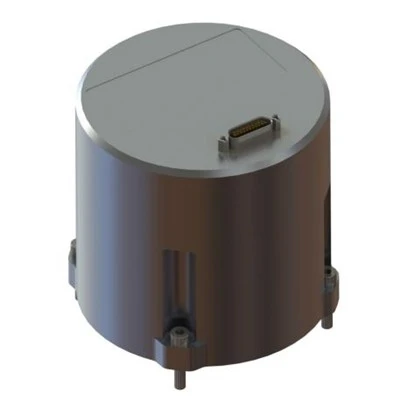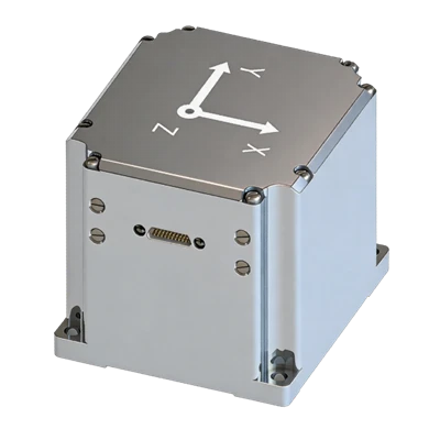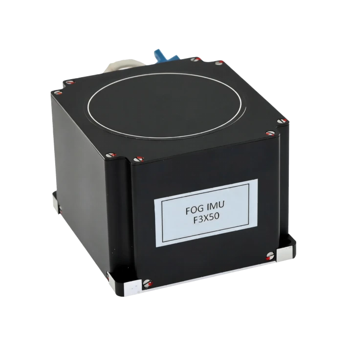
F3X50 Three-Axis Fiber Gyro IMU
All-solid-state design
Robust environmental adaptability
High reliability, ultra-long lifetime
Description
Key Features
- Compact micro design
- All-solid-state design
- Robust environmental adaptability
- High reliability, ultra-long lifetime
- Full digital RS-422 electrical interface
Applications
- Mobile survey & attitude
- Unmanned systems (ground/marine/UW)
- Surveying & north-finding
- Stabilized platforms
- SATCOM-on-the-move
- Autonomous driving & munitions
Product Introduction
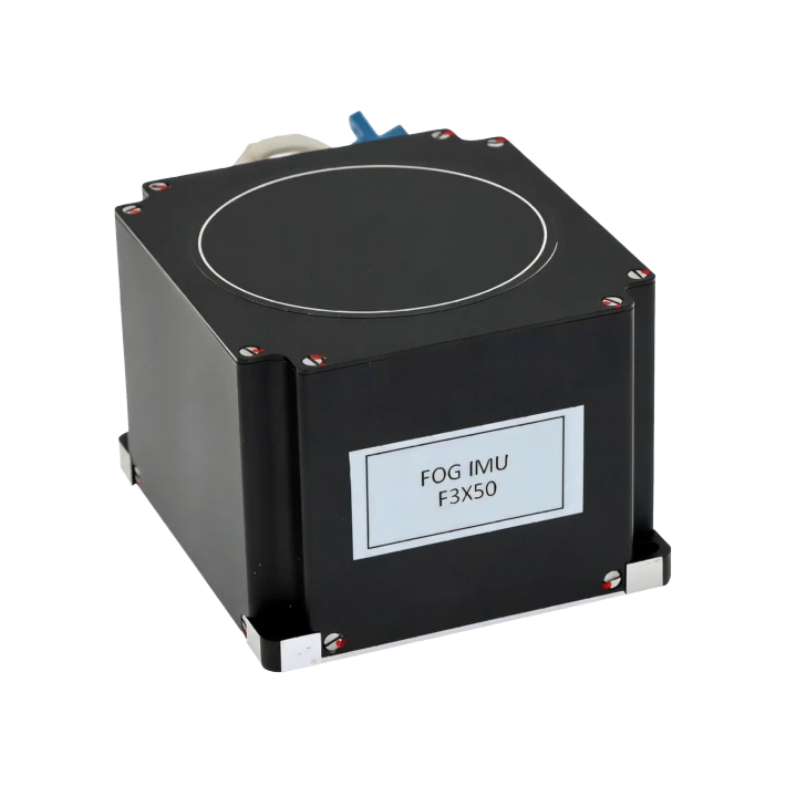
Company's F3X50 is a lightweight three-axis FOG inertial measurement unit that measures three-axis angular rates via the Sagnac effect. With a built-in low-noise three-axis MEMS accelerometer, it simultaneously outputs angular and velocity increments. Featuring an all-solid-state design with no moving parts, it delivers high precision, compact size, light weight, long service life, and high reliability, with digital interfaces for easy system integration. It is widely used in aviation, aerospace, marine, ordnance, mining, and automotive sectors for navigation, guidance, and attitude control.
Unique Technology
Company is a high-tech enterprise with full closed-loop capabilities from fiber winding equipment and coils to FOGs, fiber/MEMS inertial products, IMU circuits, software, and test equipment. End-to-end process control improves quality and reduces costs. Operating under ISO9001 with strict processes, it ensures product reliability and consistency.
F3X50 Three-Axis Fiber Optical Gyro IMU Performance Specifications
|
Parameter |
A |
B |
|
Fiber OpticGyro |
||
|
Bias Stability (°/h, 1s, 10s) |
≤0.15 |
≤0.15 |
|
Bias Repeatability (°/h, 1s, 10s) |
≤0.15 |
≤0.15 |
|
FT Bias Stability (°/h, 1s, 10s) |
≤0.5 |
≤0.5 |
|
Random Walk (°/1/2) |
≤0.02 |
≤0.02 |
|
Scale Factor Nonlinearity (ppm) |
≤50 |
≤50 |
|
Scale Factor Asymmetry (ppm) |
≤30 |
≤30 |
|
Scale Factor Repeatability (ppm) |
≤100 |
≤100 |
|
FT Scale Factor Variation (ppm) |
≤500 |
≤500 |
|
Range (°/s) |
-500~+500 |
-500~+500 |
|
MEMSAccelerometer |
||
|
0g Bias Drift (mg/°C, all axes) |
0.75 (max) |
0.75 (max) |
|
Zero Stability (g, 1s) |
≤1×10⁻⁴ |
≤1×10⁻⁴ |
|
Noise (μg/√Hz, all axes) |
80 |
80 |
|
Range (g) |
±10.24, ±20.48, ±40.96 (selectable) |
±10.24, ±20.48, ±40.96 (selectable) |
|
System |
||
|
Bandwidth (Hz) |
≥500 |
≥500 |
|
Steady-State Power (W) |
≤5.0 |
≤5.0 |
|
Insulation Resistance (MΩ) |
>100 |
>100 |
|
Weight (g) |
≤280 |
≤300 |
|
Dimensions (mm) |
67*73*49 |
87*74*56 |
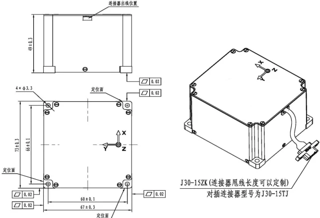
Mechanical Dimensions Diagram
Introduction
Product Overview
F3X50 fiber optic gyro IMU is a compact, lightweight, high-reliability inertial measurement device featuring high accuracy, small volume, no moving parts, high reliability, and long lifetime. Its digital output enables easy system integration for aerospace, defense, marine, weapons, mining survey, and automotive electronics applications.
1.2 Product Functions
This product is an inertial angular rate sensor based on the Sagnac principle, measuring angular rate about its sensitive axes. It provides three-axis angular increment signals.
1.3 Product Composition
The product consists of the following components:
a) Optical path: light source, coupler, Y-branch waveguide, fiber coil, detector;
b) Circuits: main board with integrated MEMS accelerometer, light source board, preamplifier board;
c) Mechanical: housing, cover, etc.
1.4 Main Performance Specifications
F3X50 fiber optic gyro IMU achieves the following performance specifications after 5 s power-on, as shown in Table 1.
Table 1 F3X50 Fiber Optic Gyro IMU Performance Specifications
|
Parameter |
A |
B |
|
Fiber OpticGyro |
||
|
Bias Stability (°/h, 1s, 10s) |
≤0.15 |
≤0.15 |
|
Bias Repeatability (°/h, 1s, 10s) |
≤0.15 |
≤0.15 |
|
FT Bias Stability (°/h, 1s, 10s) |
≤0.5 |
≤0.5 |
|
Random Walk (°/h1/2) |
≤0.02 |
≤0.02 |
|
SF Nonlinearity (ppm) |
≤50 |
≤50 |
|
SF Asymmetry (ppm) |
≤30 |
≤30 |
|
SF Repeatability (ppm) |
≤100 |
≤100 |
|
FT SF Variation (ppm) |
≤500 |
≤500 |
|
Range (°/s) |
-500~+500 |
-500~+500 |
|
MEMSAccelerometer |
||
|
0g Bias Drift (mg/°C, all axes) |
0.75 (max) |
0.75 (max) |
|
Zero Stability (g, 1s) |
≤1×10⁻⁴ |
≤1×10⁻⁴ |
|
Noise (μg/√Hz, all axes) |
80 |
80 |
|
Range (g) |
±10.24, ±20.48, ±40.96 (selectable) |
±10.24, ±20.48, ±40.96 (selectable) |
|
System |
||
|
Bandwidth (Hz) |
≥500 |
≥500 |
|
Steady-State Power (W) |
≤5.0 |
≤5.0 |
|
Insulation Resistance (MΩ) |
>100 |
>100 |
|
Weight (g) |
≤280 |
≤300 |
|
Dimensions (mm) |
67*73*49 |
87*74*56 |
1.5 Dimensions
External and mounting dimensions are shown in Figure 1. The mounting surface serves as the fixed interface; M3 screws are used.
Housing color: black anodized.
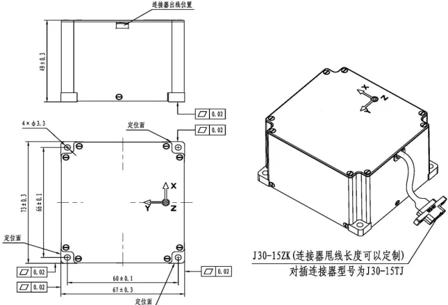
Fig. 1 F3X50Fiber Optic Gyroscope IMU Dimensions
1.6 Weight
Weight: ≤280 g
1.7 Operating Environment
Operating Temperature: -40°C to +65°C
Storage Temperature: -50°C to +75°C
Vibration: 6.06 g RMS, 10 Hz to 2000 Hz.
Interface Description
2.1 External Power and Consumption
External power supply requirements are shown in Table 2.
Table 2 External Power Requirements
|
Voltage |
Voltage Range |
Ripple |
Current |
|
+5V |
±5% |
≤50mV |
≤2.0 A(startup transient) |
|
≤1.2A(steady) |
Steady-state power: <4 W at RT, <6 W full temp; transient: <10 W (startup).
2.2 Electrical Interface
F3X50 fiber optic gyro IMU uses pigtail wiring for external electrical connections. Cable length is customizable; wire diameter: Ф0.14 mm. Pinout shown in Table 3.
Table 3 J30J-15ZK 15-Pin Connector Pinout
|
Connector (J30-15ZK) |
Pin |
Signal ID |
Signal Name |
Direction |
|
1,9 |
+5V |
Power + |
IN |
|
|
2,10 |
GND |
GND |
IN |
|
|
4 |
R+ |
RS422 RX+ |
IN |
|
|
12 |
R- |
RS422 RX- |
IN |
|
|
3 |
T+ |
RS422 TX+ |
OUT |
|
|
11 |
T- |
RS422 TX- |
OUT |
|
|
5 |
COM_GND |
422 GND |
OUT |
|
|
13 |
PPSin |
PPS Input |
Reserved |
|
|
6 |
Synclkin |
Clock Input |
Reserved |
|
|
14 |
Pulse1in |
Camera Pulse 1 |
Reserved |
|
|
7 |
Pulse2in |
Camera Pulse 1 |
Reserved |
|
|
15 |
Synclkout |
Clock Output |
Reserved |
|
|
8 |
PPSout |
PPS Output |
Reserved |
When connecting or contacting the product's connector terminals, ESD precautions must be taken per GJB 1649-1993.
2.3 Output Signal Format
Output format: RS-422;
Baud rate: 921600 bps;
Checksum: cumulative sum (bytes 3-61);
Detailed definition below:
|
Bytes |
Format |
Description |
|
0 |
Uint8 |
0x55 |
|
1 |
Uint8 |
0xAA |
|
2 |
Uint8 |
Checksum (3~61byte sum) |
|
3 |
Uint8 |
PPS(1~10,5mswhich slot0.5msreceivedPPSsignal) |
|
4~5 |
Uint16 |
Status Word (bit0andbit2both at1flagPPSreceived;bit3is camera pulse1flag) |
|
6~9 |
Uint32 |
IMU Time(5mscounter) |
|
10~13 |
Float32 |
Gx(5msang. inc., LSB: rad) |
|
14~17 |
Float32 |
Gy(5msang. inc., LSB: rad) |
|
18~21 |
Float32 |
Gz(5msang. inc., LSB: rad) |
|
22~25 |
Float32 |
Ax(5msvel. inc.,m/s) |
|
26~29 |
Float32 |
Ay(5msvel. inc.,m/s) |
|
30~33 |
Float32 |
Az(5msvel. inc.,m/s) |
|
34~35 |
int16 |
xGyro Temp (value/350 = Gyro temp ℃) |
|
36~37 |
int16 |
yGyro Temp (value/350 = Gyro temp ℃) |
|
38~39 |
int16 |
zGyro Temp (value/350 = Gyro temp ℃) |
|
40~41 |
int16 |
MEMSAccel Temp (value/350 = Accel temp ℃) |
|
42~43 |
int16 |
Reserved |
|
44~45 |
int16 |
Reserved |
|
46 |
Uint8 |
Camera Pulse1(1~10,5mswhich slot0.5msreceived signal) |
|
47~48 |
Uint16 |
Camera Pulse Time1(unit:1/40M, each count =25ns) |
|
49 |
Uint8 |
Reserved |
|
50~51 |
Uint16 |
Reserved |
|
52 |
Uint8 |
Reserved |
|
53~54 |
Uint16 |
Reserved |
|
55 |
Uint8 |
Reserved |
|
56~57 |
Uint16 |
Reserved |
|
58~59 |
Uint16 |
2kCycle Count (unit:1/40M, each count =25ns) |
|
60 |
Uint8 |
Reserved |
|
61 |
Uint8 |
Reserved |
|
62 |
Uint8 |
0xC0 |
|
63 |
Uint8 |
0xFF |
2.4 Installation
Installation Requirements
The user is responsible for installation and removal. The product must not be subjected to impacts or mechanical processing of its external surfaces during these procedures.
Pre-Installation Inspection
Inspect product exterior for physical damage such as dents;
At room temperature, verify insulation resistance ≥60 MΩ between all output connector pins and housing using a megohmmeter;
Check all electrical parameters under power if necessary;
Mounting surface flatness: better than 0.02 mm;
Post-Installation Inspection
Verify all mounting screws are securely tightened.
2.5 Maintenance
Before installation: power on at least once per year for 3600 s each; parameter monitoring is not required during this check;
After installation: power on at least once per year for 3600 s; parameter monitoring not required;
Recalibrate every 8 years (performed by the manufacturer).
2.6 Troubleshooting
This product is fully sealed and cannot be repaired on-site. Any fault must be returned to the manufacturer for repair.
The following lists potential non-product faults (see Table 4). For other technical issues, please contact the manufacturer.
Table 4 Common Faults and Troubleshooting
|
No. |
Symptom |
Root Cause |
Solution |
|
1 |
Powered on, +5V ammeter reads ~0 |
No power or insufficient supply current |
Check power supply and circuit; restore power |
|
2 |
Powered on, +5V current normal but acquisition software not functioning |
Test equipment acquisition system fault |
Check connection cables and equipment power |
|
Software conflict |
Restart test computer |
||
|
3 |
Powered on, +5V current abnormal |
Possible internal short in test equipment |
Inspect test equipment |
2.7 Transport and Storage
- Transport Precautions
- Orient the product per packaging markings;
- Transport by road, rail, air, or water is permitted within -45°C to +75°C;
- Ensure packaging is firmly secured and will not shift during transport.
- Storage Precautions
- Products in packaging should be stored under standard atmospheric pressure in air-conditioned warehouses at 15°C to 35°C with 20%-80% relative humidity;
- Storage life: 15 years.
2.8 Unpacking and Inspection
- Unpacking Inspection
- Inspect packaging for physical damage;
- Use ESD protection when removing the product.
- Delivered Documents Checklist
- Product Certificate of Conformance;
- Product Acceptance Report;
- User & Maintenance Manual (one per batch).
Hot Tags: f3x50 three-axis fiber gyro imu, China f3x50 three-axis fiber gyro imu manufacturers, factory