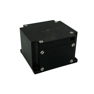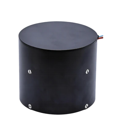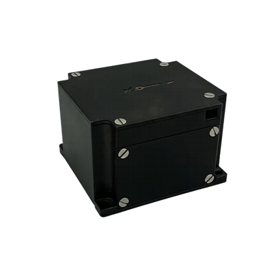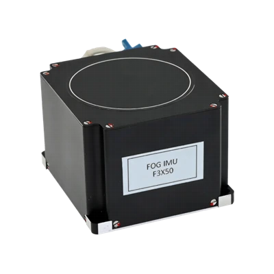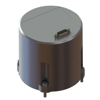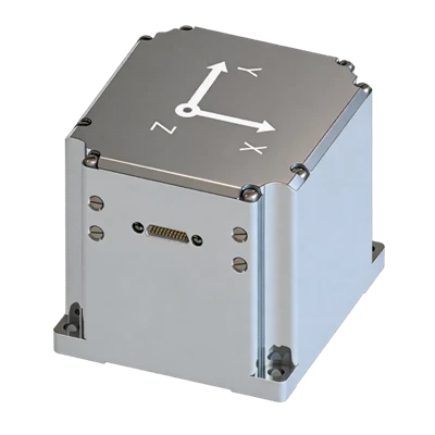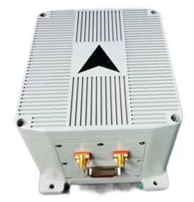
FSI301 FOG_GNSS Combined Inertial Navigation System
Domestically produced core components
High performance, small size, and low weight
High-precision FOG
Description
Main Features
- Domestically produced core components
- High performance, small size, and low weight
- High-precision FOG
- Vibration and shock resistance, EMI resistance
- Operation in harsh environments
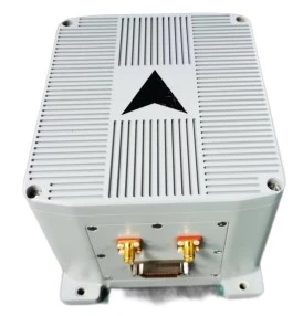
Application Fields
- Radar/infrared antenna stabilized platform
- Port surveying system
- On-the-move communication
- Attitude reference for UAVs/vehicles/ships/boats
- Attitude control
- Tunneling machine/automated coal mining
Product Overview
FSI301 is a highly reliable, cost-effective fiber-optic inertial/satellite integrated navigation system, widely applicable in fields such as high-precision vehicle-mounted platforms and long-endurance UAVs, as well as navigation, control, and measurement. The system uses closed-loop fiber optic gyroscopes (FOG) and high-precision accelerometers, combined with a professional GNSS board, to achieve real-time navigation output. The system output is compatible with mainstream post-processing software to obtain higher-precision navigation results and serve as a benchmark for research platforms.
Unique Technology
FSI301 is a highly reliable, cost-effective fiber-optic inertial/satellite integrated navigation system, widely applicable in fields such as high-precision vehicle-mounted platforms and long-endurance UAVs, as well as navigation, control, and measurement. The system uses closed-loop fiber optic gyroscopes (FOG) and high-precision accelerometers, combined with a professional GNSS board, to achieve real-time navigation output. The system output is compatible with mainstream post-processing software to obtain higher-precision navigation results and serve as a benchmark for research platforms.
FSI301 FOG_GNSS Combined Inertial Navigation System
Parameters
|
Fiber Optic Gyroscope |
|
|
Range (°/s) |
±300 |
|
Full-temperature Bias (°/h, 3σ) |
≤0.03 |
|
Bias Stability (°/h, 10 s avg.) |
≤0.03 |
|
Bias Instability (°/h, allan) |
≤0.006 |
|
MEMS Accelerometer |
|
|
Range (g) |
±30 |
|
Full-temperature Bias (mg, 3σ) |
≤0.5 |
|
Bias Stability (μg, 10s avg.) |
≤10 |
|
Bias Instability (μg, allan, typ) |
≤3 |
|
Navigation Accuracy |
|
|
North-seeking Accuracy(°,1σ) |
≤0.1secL |
|
Electrical/Mechanical Interface |
|
|
Power Supply (V) |
18~36 (ripple ≤100mV) |
|
Dimensions (mm×mm×mm) |
177*132*99 |
|
Weight (g) |
≤3500 |
Introduction
Overview
FSI301 is a highly reliable, cost-effective fiber-optic inertial/satellite integrated navigation system, widely applicable in fields such as high-precision vehicle-mounted platforms and long-endurance UAVs, as well as navigation, control, and measurement. The system uses closed-loop fiber optic gyroscopes (FOG) and high-precision accelerometers, combined with a professional GNSS board, to achieve real-time navigation output. The system output is compatible with mainstream post-processing software to obtain higher-precision navigation results and serve as a benchmark for research platforms.
Features
- Lightweight high-precision integrated navigation
- Domestically produced core components
- High performance, small size, and low weight
- Uses high-precision closed-loop fiber optic gyroscopes
- Vibration and shock resistance, and electromagnetic interference resistance
- Sealed and reliable design ensures normal operation in harsh environments
- Has inertial/GNSS integrated navigation capability
Application
- Medium- and long-endurance UAVs
- Vehicle-mounted positioning and orientation
- Radar/infrared antenna stabilized platform
- Port surveying system
- On-the-move communication
- Attitude reference for UAVs/vehicles/ships/boats
- Attitude control
- Stabilized Control and Stabilized Aiming Equipment
- Tunneling machine/automated coal mining
Technical Parameters
Table1FSI301 Performance Parameters
|
Fiber Optic Gyroscope |
|
|
Range (°/s) |
±300 |
|
Full-temperature Bias (°/h, 3σ) |
≤0.03 |
|
Bias Stability (°/h, 10 s avg.) |
≤0.03 |
|
Bias Instability (°/h, allan) |
≤0.006 |
|
Bias Repeatability (°/h) |
≤0.03 |
|
Angle Random Walk (°/√h) |
≤0.003 |
|
Scale Factor Nonlinearity (ppm) |
≤30 |
|
Cross-coupling (rad) |
≤0.001 |
|
Bandwidth (Hz) |
≥200Hz |
|
MEMS Accelerometer |
|
|
Range (g) |
±30 |
|
Full-temperature Bias (mg, 3σ) |
≤0.5 |
|
Bias Stability (μg, 10s avg.) |
≤10 |
|
Bias Instability (μg, allan, typ) |
≤3 |
|
Bias Repeatability (µg) |
≤10 |
|
Velocity Random Walk (m/s/√h) |
≤0.01 |
|
Scale Factor Nonlinearity (ppm, ±1g) |
≤100 |
|
Cross-coupling (rad) |
≤0.001 |
|
Bandwidth (Hz) |
≥200Hz |
|
Navigation Accuracy |
|
|
North-seeking Accuracy(°,1σ) |
0.1secL |
|
Combination Horizontal Position (m, 1σ) |
≤2(single point), ≤0.02+1ppm (RTK) |
|
Combination Heading Position (m,1σ) |
≤3 (single point), ≤0.03+1ppm (RTK) |
|
Combination Horizontal Velocity (m/s, 1σ) |
≤0.05 |
|
Combination Vertical Velocity (m/s, 1σ) |
≤0.1 |
|
Combination Heading (°, 1σ)) |
≤0.1 (dynamic) ≤0.05 (RTK, dynamic) |
|
Combination Horizontal Attitude (°, 1σ) |
≤0.01 (single-point, dynamic) ≤0.007 (RTK, dynamic) |
|
Pure Inertial Accuracy (1σ) |
1nmile/30min |
|
Depth Measurement Accuracy |
≤5 cm (marine environment) |
|
Electrical/Mechanical Interface |
|
|
Power Supply (V) |
18~36 (ripple ≤100mV) |
|
Steady-state Power (W) |
≤15 |
|
Startup Time (s) |
≤2 |
|
Communication Interface |
RS422/RS232/USB/CAN |
|
Update Rate (Hz) |
200 |
|
Dimensions (mm×mm×mm) |
177*132*99 |
|
Weight (g) |
3500 |
|
Operating Environment |
|
|
Operating Temperature (°C) |
-40 to +60 |
|
Storage Temperature (°C) |
-55 to +85 |
|
Vibration (g, Rms) |
20~2000HZ, 6.06 |
|
Shock (g) |
100g/1ms |
|
Reliability |
|
|
MTBF (h) |
75000+ |
Note: The receiver can be replaced with one that has satellite-based differential capability, with positioning accuracy better than 10 cm.
Technical Specifications
Structure
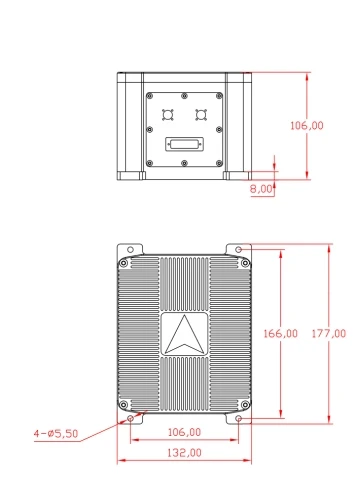
FSI301 measures 177 × 132 × 99 mm and is mounted using M5 screws.
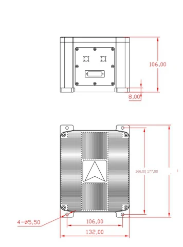
Figure1 Mechanical interface diagram of the FSI301 inertial/satellite integrated navigation system
The GNSS receiver antenna provides a standard model size: 154 mm × 154 mm × 64.2 mm.
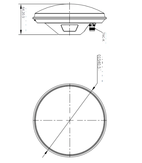
Figure2 Mechanical interface diagram of the FSI301 system satellite antenna
The GNSS receiver antenna provides a strong magnetic suction base, with dimensions of 100 mm × 100 mm × 66 mm.
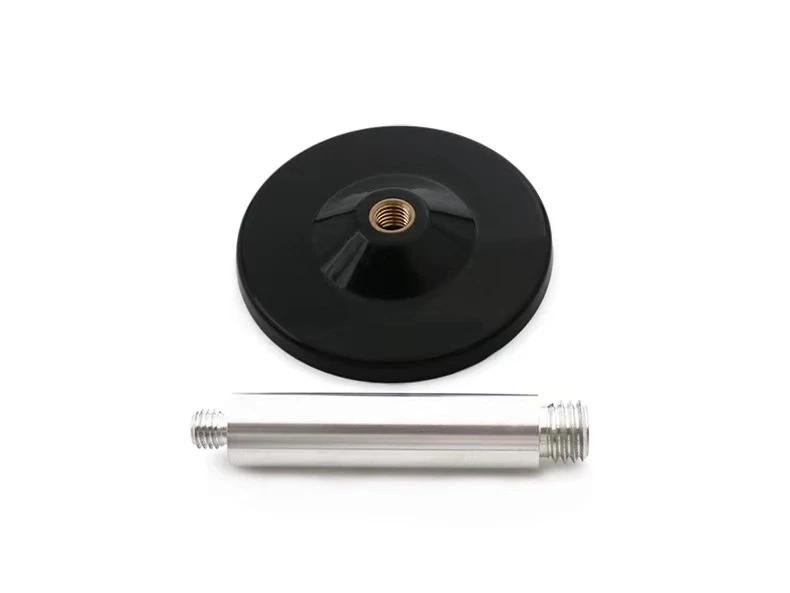
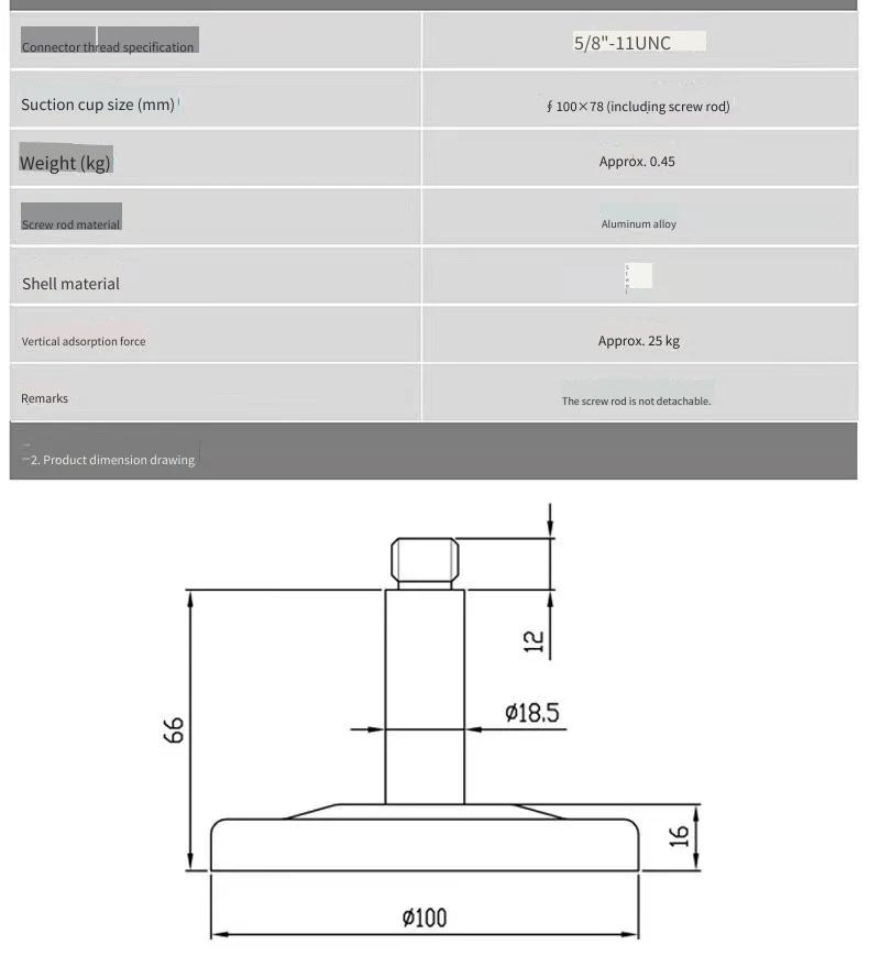
Figure3 Magnetic suction base diagram of the FSI301 system satellite antenna
Product Marking/Polarity
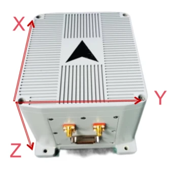
With the product placed horizontally, the arrow indicates the X direction, and the output coordinate system is the "front, right, down" coordinate system.
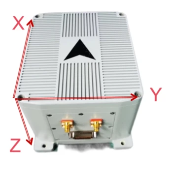
Figure4 coordinate System
Interface Definitions
The FSI301 dual satellite antenna connector is a standard SMA male connector, with the left side being the positioning antenna and the right side being the directional antenna.
FSI301 uses a J30J-51ZKW electrical connector, and the corresponding plug uses J30J-51TJL. The external interface definitions are shown in the table below:
Table2 FSI301 system interface cable pin definition
|
Serial No. |
Pin number |
Description |
Meaning |
External connection method |
|
1 |
27 |
VIN |
External 24V power supply |
Red clip |
|
2 |
28 |
VIN |
||
|
3 |
1 |
GND |
Black clip |
|
|
4 |
2 |
GND |
||
|
5 |
44 |
LCJ_G5V |
External odometer interface (incremental odometer) |
Separate wire |
|
6 |
45 |
LCJ_GGND |
||
|
7 |
19 |
LCJ_B |
||
|
8 |
20 |
LCJ_A |
||
|
9 |
32 |
INS_RS422_RX+ |
External inertial navigation RS422 main interface, can be used to configure the protocol and upload core0 navigation software. |
DB9-M1-1 |
|
10 |
6 |
INS_RS422_RX- |
DB9-M1-2 |
|
|
11 |
4 |
INS_RS422_TX+ |
DB9-M1-3 |
|
|
12 |
30 |
INS_RS422_TX- |
DB9-M1-4 |
|
|
13 |
3 |
GGND1 |
DB9-M1-5 |
|
|
14 |
33 |
JK_COMM1_RX+ |
ExternalRS422isolated interface, can be used to configure protocols, uploadcore1interface software |
DB9-M2-1 |
|
15 |
7 |
JK_COMM1_RX- |
DB9-M2-2 |
|
|
16 |
5 |
JK_COMM1_TX+ |
DB9-M2-3 |
|
|
17 |
31 |
JK_COMM1_TX- |
DB9-M2-4 |
|
|
18 |
8 |
GGND1 |
DB9-M2-5 |
|
|
19 |
17 |
BY_COMM2_RX+ |
External spare RS422 isolated interface |
DB9-M3-1 |
|
20 |
42 |
BY_COMM2_RX- |
DB9-M3-2 |
|
|
21 |
41 |
BY_COMM2_TX+ |
DB9-M3-3 |
|
|
22 |
16 |
BY_COMM2_TX- |
DB9-M3-4 |
|
|
23 |
18 |
GGND1 |
DB9-M3-5 |
|
|
24 |
10 |
INS_RS232_TXD |
External inertial navigation RS232 isolated interface, can be used to configure protocols and output externally 232 Protocol |
DB9-M4-2 |
|
25 |
36 |
INS_RS232_RXD |
DB9-M4-3 |
|
|
26 |
34 |
GGND1 |
DB9-M4-5 |
|
|
27 |
9 |
IMU_RS232_TXD |
External IMU RS232 Isolated Interface |
DB9-M5-2 |
|
28 |
35 |
IMU_RS232_RXD |
DB9-M5-3 |
|
|
29 |
29 |
GGND1 |
DB9-M5-5 |
|
|
30 |
15 |
GPS_CFG_TXD |
External GPS RS232 configuration interface, supports differential positioning. |
DB9-M6-2 |
|
31 |
40 |
GPS_CFG_RXD |
DB9-M6-3 |
|
|
32 |
39 |
GGND1 |
DB9-M6-5 |
|
|
33 |
11 |
PPS_OUT+ |
PPS second-pulse output isolated interface (differential & single-ended TTL) |
DB9-M7-1 |
|
34 |
37 |
PPS_OUT- |
DB9-M7-2 |
|
|
35 |
43 |
GGND1 |
DB9-M7-7 |
|
|
36 |
12 |
IO_IN |
PPS pulse input isolated interface (PPS+ can be reused as single-ended LVTTL output) |
DB9-M8-9 |
|
37 |
13 |
PPS_IN+ |
DB9-M8-3 |
|
|
38 |
38 |
PPS_IN- |
DB9-M8-4 |
|
|
39 |
14 |
GGND1 |
DB9-M8-5 |
|
|
40 |
22 |
CAN1H |
External CAN bus isolated interface1 |
DB9-M9-7 |
|
41 |
47 |
CAN1L |
DB9-M9-2 |
|
|
42 |
48 |
GGND2 |
DB9-M9-3 |
|
|
43 |
21 |
CAN2H |
External CAN bus isolated interface2 |
DB9-M10-7 |
|
44 |
46 |
CAN2L |
DB9-M10-2 |
|
|
45 |
25 |
USB_DM |
USB interface |
Separate wire |
|
46 |
51 |
USB_DP |
||
|
47 |
26 |
USB_GND |
||
|
48 |
23 |
ETH_TXD_P |
100Mbps Ethernet interface |
Separate wire |
|
49 |
49 |
ETH_TXD_N |
||
|
50 |
24 |
ETH_RXD_P |
||
|
51 |
50 |
ETH_RXD_N |
After the power supply voltage drops below the device operating threshold voltage, the power-off hold time tOFF before the next power-on shall not be less than 3 s; insufficient power-off interval may cause abnormal device startup, latch-up, or initialization failure.
External communication
Protocol 1: Integrated Navigation Data Protocol
FSI301 default timed broadcast output data, output frequency 200Hz, each frame of data164bytes, baud rate 460800bps,1start bits,8data bits,1stop bits, no parity. Data transmission uses a little-endian data format with the least significant byte first. A typical communication protocol is shown as follows; the communication protocol can also be customized according to user requirements.
Table3Integrated Navigation System Output Communication Protocol
|
Serial No. |
First byte order |
Number of bytes |
Signal Name |
Dimensional unit or content |
Equivalent |
Interface accuracy description |
|
1 |
0 |
1 |
Header 1 |
Content: 55H |
1 |
8-bit unsigned integer |
|
2 |
1 |
1 |
Header 2 |
Content: AAH |
1 |
8-bit unsigned integer |
|
3 |
2 |
1 |
Data length |
Content: A0H |
1 |
8-bit unsigned integer |
|
4 |
3 |
4 |
PCNum |
Interrupt counter |
1 |
32-bit unsigned integer |
|
5 |
7 |
1 |
System status word |
- |
1 |
Self-test in progress: 0x10 self-test passed: 0x12 self-test error: 0x1F coarse alignment: 0x33 fine alignment: 0x35 pure inertial navigation: 0x41 zero-velocity correction: 0x43 Velocity + position combined: 0x44 Velocity + position + heading combined: 0x45 Vehicle-constrained navigation: 0x46 Odometer combined navigation: 0x47 during self-calibration: 0x51, 0x53, 0x55 Self-calibration completed, criteria valid: 0x56 Self-calibration written to Flash successfully: 0x57 Self-calibration error: 0x5F. |
|
6 |
8 |
1 |
Real-time status word |
- |
1 |
|
|
7 |
9 |
2 |
Reserved byte |
- |
1 |
|
|
8 |
11 |
4 |
Reserved byte |
- |
1 |
|
|
9 |
15 |
4 |
X gyroscope angular velocity |
[-1000, 1000]°/s, |
0.0000005 |
Average within the output period |
|
10 |
19 |
4 |
Y gyroscope angular velocity |
[-1000, 1000]°/s, |
0.0000005 |
Average within the output period |
|
11 |
23 |
4 |
Z gyroscope angular velocity |
[-1000, 1000]°/s, |
0.0000005 |
Average within the output period |
|
12 |
27 |
4 |
X accelerometer acceleration |
[-400m/s2,400m/s2] |
0.000001 |
Average within the output period |
|
13 |
31 |
4 |
Y accelerometer acceleration |
[-400m/s2,400m/s2] |
0.000001 |
Average within the output period |
|
14 |
35 |
4 |
Z accelerometer acceleration |
[-400m/s2,400m/s2] |
0.000001 |
Average within the output period |
|
15 |
39 |
4 |
Combined longitude |
(-180,180]deg |
0.0000001 |
|
|
16 |
43 |
4 |
Combined latitude |
[-90,90]deg |
0.0000001 |
|
|
17 |
47 |
4 |
Combined altitude |
[-500,16384]m |
0.00001 |
|
|
18 |
51 |
2 |
Combined North Velocity |
[-1310,1310]m/s |
0.005 |
|
|
19 |
53 |
2 |
Combined Up Velocity |
[-1310,1310]m/s |
0.005 |
|
|
20 |
55 |
2 |
Combined East Velocity |
[-1310,1310]m/s |
0.005 |
|
|
21 |
57 |
2 |
Roll Angle |
[-90,90]deg |
0.006 |
|
|
22 |
59 |
2 |
Heading Angle |
[-180,180]deg |
0.006 |
West of north is positive |
|
23 |
61 |
2 |
Pitch angle |
[-85,85] you |
0.006 |
|
|
24 |
63 |
4 |
Satellite longitude |
(-180,180]deg |
0.0000001 |
|
|
25 |
67 |
4 |
Satellite latitude |
[-90,90]deg |
0.0000001 |
|
|
26 |
71 |
4 |
Satellite altitude |
[-500,16384]m |
0.00001 |
|
|
27 |
75 |
2 |
Satellite north velocity |
[-1310,1310]m/s |
0.005 |
|
|
28 |
77 |
2 |
Satellite upward velocity |
[-1310,1310]m/s |
0.005 |
|
|
29 |
79 |
2 |
Satellite east velocity |
[-1310,1310]m/s |
0.005 |
|
|
30 |
81 |
1 |
Temperature |
[-127,127] |
1 |
|
|
31 |
82 |
1 |
Positioning and orientation validity |
/ |
1 |
bit0-3, receiver positioning flag: 00 no positioning, 01 single-point positioning, 02 float solution positioning, 03 fixed solution positioning; bit4-7, orientation signal: 00 no orientation, 01 single-point orientation, 02 float solution orientation, 03 fixed solution orientation. |
|
32 |
83 |
4 |
Satellite time of week in seconds |
|||
|
33 |
87 |
1 |
Year |
|||
|
34 |
88 |
1 |
Month |
|||
|
35 |
89 |
1 |
Day |
|||
|
36 |
90 |
1 |
Number of positioning satellites |
[0,255] |
1 |
|
|
37 |
91 |
2 |
Satellite track angle |
[-180,180]deg |
0.006 |
|
|
38 |
93 |
2 |
Dual-antenna heading |
[-180,180]deg |
0.006 |
|
|
39 |
95 |
2 |
Reserved |
|||
|
40 |
97 |
14 |
Reserved |
|||
|
41 |
111 |
12 |
Reserved |
|||
|
42 |
123 |
4 |
AU |
m/s² |
1 |
Upward acceleration |
|
43 |
127 |
4 |
AF |
m/s² |
1 |
Forward acceleration |
|
44 |
131 |
4 |
AR |
m/s² |
1 |
Rightward acceleration |
|
45 |
135 |
4 |
heave |
m |
1 |
Relative heave displacement |
|
46 |
139 |
4 |
Filtered output |
na |
1 |
|
|
47 |
143 |
4 |
Filtered input |
na |
1 |
|
|
48 |
147 |
4 |
Main frequency |
na |
1 |
|
|
49 |
151 |
4 |
Integer part of the data time |
- |
- |
|
|
50 |
155 |
4 |
Fractional part of the data time |
- |
- |
|
|
51 |
159 |
4 |
Reserved |
- |
1 |
|
|
52 |
163 |
1 |
Checksum |
Low 8 bits of the sum of the data length and the data bytes |
1 |
Protocol 2: IMU Protocol
The backup IMU protocol outputs IMU data by default in timed broadcast mode. Each frame contains 40 bytes of data, the default output frequency is 200Hz, the baud rate is 115200bps, with 1 start bit, 8 data bits, 1 stop bit, and no parity.The data transmission uses a little-endian format with the low byte first. The baud rate and output frequency of the communication protocol can be configured.
Table4General IMU Protocol
|
Serial No. |
Byte start index |
Number of bytes |
Content |
Equivalent |
Range |
Unit |
Remark |
|
1 |
0 |
1 |
0x55 |
1 |
Frame header |
||
|
2 |
1 |
1 |
0xAA |
1 |
Frame header |
||
|
3 |
2 |
1 |
36 |
1 |
Data length |
||
|
4 |
3 |
4 |
PCnum |
1 |
1 ms count value |
||
|
5 |
7 |
4 |
Angular rate X |
0.000001 |
[-2000,2000] |
/s |
|
|
6 |
11 |
4 |
Angular rate Y |
0.000001 |
[-2000,2000] |
/s |
|
|
7 |
15 |
4 |
Angular rate Z |
0.000001 |
[-2000,2000] |
/s |
|
|
8 |
19 |
4 |
Acceleration X |
0.000001 |
[-40,40] |
m/s² |
|
|
9 |
23 |
4 |
Acceleration Y |
0.000001 |
[-40,40] |
m/s² |
|
|
10 |
27 |
4 |
Acceleration Z |
0.000001 |
[-40,40] |
m/s² |
|
|
11 |
31 |
2 |
System temperature |
0.008 |
[-120,120] |
℃ |
|
|
12 |
33 |
2 |
Year Month Day |
- |
- |
- |
Bit0~bit4: day 0-31 Bit5~bit8: month 0~12 Bit9~bit15: year 0~99 For example, 1100011110011111 represents December 31, 2099 |
|
13 |
35 |
4 |
Timestamp |
0.1 |
- |
ms |
(h*3600+m*60+s)*10000 Example: 110011011111111001011111111111 Represents: 23h59min59.9999s |
|
14 |
39 |
1 |
Checksum |
1 |
[0,255] |
Low 8 bits of the cumulative sum of bytes at indices (2–38) |
GNSS Protocol
GNSS receiver configuration parameter list:
mode rover
CONFIG HEADING FIXLENGTH
CONFIG PPS ENABLE2 GPS POSITIVE 1000 1000 0 0
config com1 115200 n 1
config com2 460800 8 n 1
config com3 460800 8 n 1
GPGGA COM1 1
RANGECMPB com1 1
BD2EPHEMB com1 290
GPSEPHEMB com1 300
BESTPOSB COM1 1
KSXT COM2 0.1
GPGGA COM2 0.1
GPGGA COM3 1
RANGECMPB com3 1
BD2EPHEMB com3 290
GPSEPHEMB com3 300
BESTPOSB COM3 0.2
Inside the GNSS receiver:
The receiver COM1 port is an external output port, which can receive differential corrections and store differential data;
The receiver COM2 is the internal solution port;
The receiver COM3 port is the stored data output port, and the stored GNSS files can be decoded using GINS or decoded using the official decoding software from Unicore.
Decode it into RINEX-format data of version 3.02 or above for post-processing.
If you need the receiver to configure other types of output, please refer to Unicore Reference Commands Manual For N4 High Precision Products_V2_CH_R1.4.
Product precautions
- Pay attention to the product electrical interface definitions. When using it, strictly follow the pin arrangement to avoid incorrect connections;
- The product is a precision measuring device. During operation, be careful to avoid shocks, collisions, and other conditions beyond the product's tolerance range;
- The installation of the product has a great impact on angular velocity measurement. To avoid introducing installation errors, the mounting surface is required to have good flatness;
- To ensure measurement accuracy, the product must be installed firmly and reliably to avoid measurement errors caused by loosening;
- When installing and using the product, attention should be paid to electrostatic protection; wearing an antistatic wrist strap is recommended;
- Please operate strictly in accordance with the requirements of this manual, and confirm that the external environment is consistent with the usage requirements. If a problem occurs, do not disassemble the product cover or alter the internal structure of the product. If there is any issue, please contact and communicate with our technical personnel in a timely manner.
Hot Tags: fsi301 fog_gnss combined inertial navigation system, China fsi301 fog_gnss combined inertial navigation system manufacturers, factory