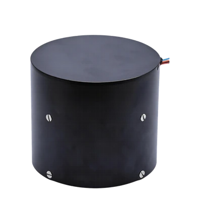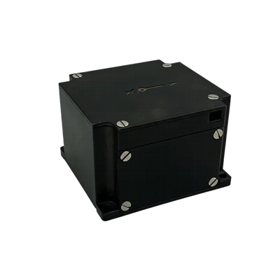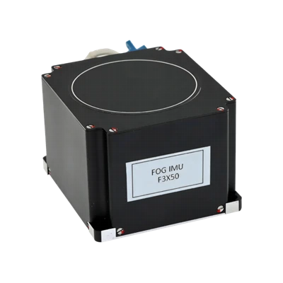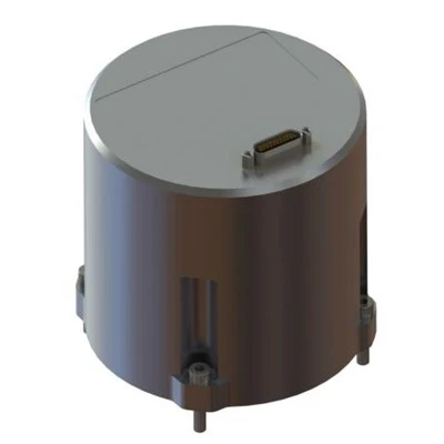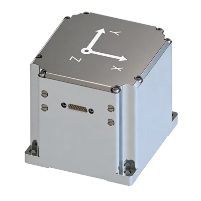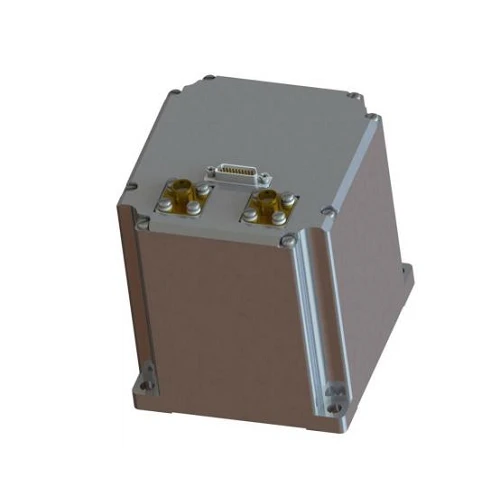
FSI206 FOG Strapdown Inertial Navigation System
Domestic core parts, light modular, high performance
-40~70℃ calibrated, 10W low power
Full-band GNSS+RTK, satellite-free attitude correction
Description
Main Features
- Domestic core parts, light modular, high performance
- -40~70℃ calibrated, 10W low power
- Full-band GNSS+RTK, satellite-free attitude correction
- Shock/vibration/EMI resistant, harsh-environment ready
- Multi-port, online upgrade
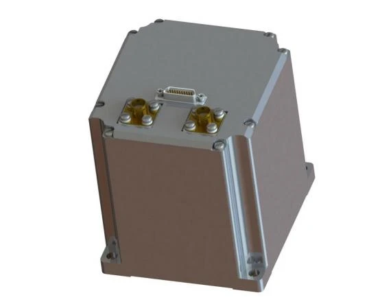
Application Fields
- Mobile survey position & attitude reference
- UGV, USV
- Mapping
- Stabilized platform
- Underwater vehicle
- SATCOM on the move
- Autonomous driving
- Missile-borne control
- Intelligent mine north-seeking
Product Overview
FSI206 is a highly reliable and cost-effective navigation system with a built-in receiver, and can be widely used in navigation, control, measurement, and other fields represented by aircraft, unmanned vehicles, unmanned boats, and unmanned aerial vehicles.
Unique Technology
The system inherits the modular design philosophy of similar products and adopts high-precision silicon optical gyroscopes and high-precision MEMS accelerometers. Through multi-sensor fusion algorithm processing, the main inertial navigation data and GPS position and velocity are input into the filter, while the INS position, velocity, and attitude are also used as inputs to the filter. By comparing the difference between the two, the filter establishes an error model to estimate INS errors and uses these errors to correct the inertial navigation results, thereby obtaining integrated navigation results for velocity, position, and attitude. The inertial navigation system can provide different configuration modes to suit different carriers, such as airborne, vehicle-mounted, and shipborne.
Parameters
FSI206 FOG Strapdown Inertial Navigation System
|
Fiber Optic Gyroscope |
|
|
Range (° /s) |
±500 |
|
Bias Stability (° /h, 10s) |
0.5 |
|
Bias Instability (°/h, allan, typ) |
≤0.05 |
|
Bias Repeatability (°/h,6 times power-up) |
0.5 |
|
FM Accelerometer |
|
|
Range (g) |
30 |
|
Full-temperature Bias (mg,3σ) |
0.5 |
|
Integrated Navigation Accuracy |
|
|
Self North-seeking Accuracy(°,1σ) |
1secL |
|
Pure Inertial Accuracy (1σ) |
300m/300s |
|
Combined heading accuracy (° ,1 σ, real-time) |
0.5 |
|
Combined horizontal attitude (° ,1σ, real-time)) |
0.06 |
|
Combined horizontal position (m ,1 s) |
3(single point), 0.02+1ppm (RTK) |
|
Satellite Receiver (Built-In) |
|
|
Satellite Mode |
GPS:L1/L2/L5 BeiDou:B1/B2/B3 GLONASS:L1/L2 |
|
Electrical / Mechanical Interfaces |
|
|
Power (V) |
12~36VDC (recommended 24V) |
|
Steady-state Power (W) |
10W |
|
Dimensions (mm×mm×mm) |
65×70×63 |
|
Weight (g) |
≤500 |
Introduction
Overview
FSI206 is a highly reliable and cost-effective navigation system with a built-in receiver, and can be widely used in navigation, control, measurement, and other fields represented by aircraft, unmanned vehicles, unmanned boats, and unmanned aerial vehicles.
The integrated navigation system inherits the modular design philosophy of similar products and adopts high-precision silicon optical gyroscopes and high-precision MEMS accelerometers. Through multi-sensor fusion algorithm processing, the main inertial navigation data and GPS position and velocity are input into the filter, while the INS position, velocity, and attitude are also used as inputs to the filter. By comparing the difference between the two, the filter establishes an error model to estimate INS errors and uses these errors to correct the inertial navigation results, thereby obtaining integrated navigation results for velocity, position, and attitude. The inertial navigation system can provide different configuration modes to suit different carriers, such as airborne, vehicle-mounted, and shipborne. In vehicle-mounted applications, vehicle constraints are added, and through error estimation and correction, long-duration high-precision navigation and positioning of the carrier is achieved.
FSI206 can be configured with different software functions according to user requirements. In view of the characteristics of some inertial navigation industry applications, functions such as transfer alignment, integrated navigation, pure inertial navigation computation, and heading and attitude can be carried out, thereby meeting the needs of different users to the greatest extent.
Composition
FSI206 mainly consists of a three-axis silicon optical gyroscope, high-precision FM accelerometer, information processing circuit, navigation software, structural components, test cables, receiver board (optional), GNSS antenna (optional), and feeder cable (optional). The main components include:
Table 1 Main Components of FSI206
|
No. |
Component |
Quantity |
Model |
Remarks |
|
1 |
High-Precision Inertial Navigation System |
1 |
FS206 |
|
|
2 |
Connector Plug |
1 |
J20JD-21TJL |
Male Connector |
|
3 |
Receiver Board |
1 |
Optional |
|
|
4 |
GNSS Antenna |
2 |
BT-800S |
Optional Magnetic Base or Screw Fastening |
|
5 |
GNSS antenna cable |
2 |
TNC male - SMA male |
Optional 5 m |
Features
The main features of FSI206 are as follows:
- Core components are domestically produced, with high performance, modularity, and low weight
- Supports all GNSS frequency bands, with high positioning and orientation accuracy in complex environments
- Rich interfaces
- 10W power consumption during steady-state operation
- Full-temperature calibration compensation from -40℃ to +70℃
- Resistant to harsh mechanical environments
- Resistant to vibration, shock, and electromagnetic interference
- Supports online software upgrade and installation error compensation
- Self-correction algorithm without GNSS, maintaining horizontal attitude accuracy
- Can connect to RTK differential correction
- Zero-speed correction and vehicle constraint algorithms improve autonomous accuracy
Application
The main application fields of FSI206 are as follows:
- Position and attitude reference for mobile surveying
- Unmanned vehicles, unmanned ships / vessels
- Surveying and mapping
- Stabilized platform
- Underwater vehicle
- Communications on the move
- Intelligent driving
- Missile-borne control
- Intelligent mine north seeking
System Specification
Table 2 FSI206 Parameters
|
Fiber Optic Gyroscope |
|
|
Range (° /s) |
±500 |
|
Bias (° /h) |
≤1 |
|
Bias Stability (° /h, 10s avg.) |
≤0.5 |
|
Bias Instability (°/h, allan, typ) |
≤0.05 |
|
Bias Repeatability (°/h,6 times power-up) |
≤0.5 |
|
Angle Random Walk (°/√h) |
≤0.05 |
|
Scale Factor Nonlinearity (ppm) |
≤200 |
|
Cross Coupling (rad) |
≤0.001 |
|
Bandwidth (Hz) |
≥200 |
|
FM Accelerometer |
|
|
Range (g) |
±30 |
|
Full-temperature Bias (mg,3σ) |
≤0.5 |
|
Bias Stability (μg,10s smoothed) |
≤10 |
|
Bias Instability (μg, allan,typ) |
≤3 |
|
Bias Repeatability (ug) |
≤10 |
|
Velocity Random Walk (m/s/√h) |
≤0.01 |
|
Scale Factor Nonlinearity (ppm, ±1g) |
≤100 |
|
Cross Coupling (rad) |
≤0.001 |
|
Bandwidth (Hz) |
≥200Hz |
|
Integrated Navigation Accuracy |
|
|
Self North-seeking Accuracy(°,1σ) |
≤1secL |
|
Pure Inertial Accuracy (1σ) |
≤300m/300s |
|
Combined Heading Accuracy (° ,1 σ, real-time) |
0.5 |
|
Combined Horizontal Attitude (° ,1σ, real-time)) |
0.06 |
|
Combined Horizontal Position (m ,1σ) |
3(single point), 0.02+1ppm (RTK) |
|
Combined Vertical Position (m ,1σ) |
5(single point), 0.03+1ppm (RTK) |
|
Combined Horizontal Velocity (m/s,1σ) |
0. 1 |
|
Combined Vertical Velocity (m/s,1σ) |
0.15 |
|
Satellite Receiver (Built-In) |
|
|
Timing accuracy |
20ns |
|
Cold Start Positioning Time |
≤40s |
|
Startup Time |
≤2s |
|
Positioning Data Update Rate |
10Hz |
|
Operating Altitude |
10000m |
|
Satellite Mode |
GPS:L1/L2/L5 BeiDou:B1/B2/B3 GLONASS:L1/L2 |
|
Electrical / Mechanical Interfaces |
|
|
Power (V) |
12~36VDC (recommended 24V) |
|
Steady-state Power (W) |
≤10W |
|
Startup Time (s) |
3 |
|
Communication Interface |
RS-422 |
|
Update Rate (Hz, max) |
1000(IMU),200(INS) |
|
Dimensions (mm×mm×mm) |
65×70×63 |
|
Weight (g) |
≤500 |
|
Operating Environment |
|
|
Operating Temperature |
-40~70 |
|
Storage Temperature |
-55~85 |
|
Vibration |
20~2000HZ, 6.06 |
|
Shock |
100/1ms |
Mechanical Interface
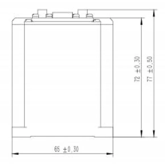
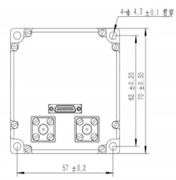
FSI206 Mechanical Interface is shown in the figure:
Weight of the integrated navigation system (excluding the GNSS antenna and feeder cable): ≤ 500g;
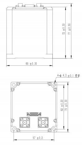
Figure 1 Mechanical Interface Diagram of FSI206
The GNSS receiver antenna provides standard model dimensions:65mm70mm63mm, the base uses 5 M4 screws fastening.
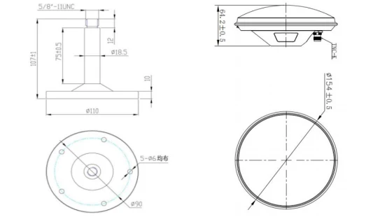
Figure 2 FSI206 Satellite Antenna Mechanical Interface
The GNSS receiver antenna is provided with a strong magnetic base, with dimensions of 100mm × 100mm × 66mm.
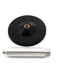
Figure 3 FSI206 Satellite Antenna Magnetic Base
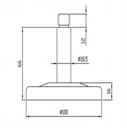
Figure 4 FSI206 Satellite Antenna Magnetic Base
Electrical Interface
The external interface of FSI206 uses a J20JD-21ZKP electrical connector, and the corresponding plug uses J20JD-21TJL. The definition of the external interface is shown in the table below:
Table 3 FSI206 Interface Cable Pin Number Definition
|
Contacts |
PIN Definition |
External DB9 |
Type |
Remarks |
|
1. |
+ VIN |
External 24V Power Supply |
Power Supply |
Red Clip |
|
2. |
GND |
Power Supply |
Black Clip |
|
|
3. |
COM1_Rx+ |
External RS422 non-isolated interface 1 |
Receives the aircraft's main inertial navigation system |
DB9-M1-1 |
|
4. |
COM1_Rx - |
DB9-M1-2 |
||
|
5. |
COM1_Tx+ |
Send integrated navigation information |
DB9-M1-3 |
|
|
6. |
COM1_Tx - |
DB9-M1-4 |
||
|
7. |
GND |
DB9-M1-5 |
||
|
8. |
COM2_Tx+ |
External RS422 non-isolated interface 2 |
Send the raw data output by the inertial navigation IMU |
DB9-M2-3 |
|
9. |
COM2_Tx - |
DB9-M2-4 |
||
|
10. |
GND |
DB9-M2-5 |
||
|
11. |
COM2_PPS_IN+ |
PPS differential input interface, non-isolated |
Composite pulse input |
DB9-M3-1 |
|
12. |
COM2_PPS_IN- |
DB9-M3-2 |
||
|
13. |
COM3_PPS_OUT+ |
PPS differential output interface, non-isolated |
Differential pulse-per-second output |
DB9-M3-3 |
|
14. |
COM3_PPS_OUT- |
DB9-M3-4 |
||
|
15. |
GND |
DB9-M3-5 |
||
|
16. |
COM3_Rx+ |
External RS422 non-isolated interface 4 |
DB9-M4-1 |
|
|
17. |
COM3_Rx - |
DB9-M4-2 |
||
|
18. |
GND |
DB9-M4-5 |
||
|
19. |
RS232_TXD1 |
External RS232 non-isolated interface 1 |
Debug port, upgrade firmware |
DB9-M5-2 |
|
20. |
RS232_RXD1 |
DB9-M5-3 |
||
|
21. |
GND |
DB9-M5-5 |
Data Protocols and Parsing
Protocol 1: Host Computer to Inertial Navigation Command Protocol
After the integrated navigation system passes self-check, it can receive valid corresponding user commands and execute the corresponding functions according to protocol constraints, as detailed in the table below.
Table 4 FSI206 User Host Computer Transmission Protocol
|
Content |
Source |
Electro-optical pod |
||
|
Target |
IMU (including processing board) |
|||
|
Transmission period |
Frame rate 200HZ |
|||
|
Transmission rate |
460800bps |
|||
|
Serial No. |
Symbol |
Number of bytes |
Content |
Data Definition |
|
1 |
Head1 |
1 |
Frame Header 1 |
0xEB |
|
2 |
Head2 |
2 |
Frame Header 2 |
0x90 |
|
3 |
3~4 |
Reserved |
||
|
4 |
ωYaw |
5~6 |
Main inertial navigation Z-axis angular rate |
Int16, resolution 300/215, unit: °/s, pointing downward, right turn is positive. |
|
5 |
ωPitch |
7~8 |
Main INS X-axis angular rate |
Int16, resolution 300/215, unit: °/s, pointing to the right, nose-up is positive. |
|
6 |
ωRoll |
9~10 |
Main INS Y-axis angular rate |
Int16, resolution 300/215, unit: °/s, pointing forward, right roll is positive. |
|
7 |
Stars |
11 |
Number of positioning satellites |
|
|
8 |
PDOP |
12 |
Navigation accuracy factor |
1-100 |
|
9 |
NOSE |
13 |
Main INS status |
0x11, integrated navigation data valid; 0x22, pure inertial navigation data valid; 0x33, navigation data invalid; 0x44, alignment data; Note: 0x11 and 0x22 indicate the main INS is valid; 0x33 and 0x44 indicate the main INS is invalid. All information. |
|
10 |
Yaw |
14~15 |
Main INS yaw angle |
Low byte first, then high byte 16 bit unsigned integer 0~ 359.99º LSB = 0.01º (north is0, east is 90º) |
|
11 |
Pitch |
16~17 |
Main INS pitch angle |
Low byte first, then high byte 16 bit signed integer -89.99 º~+89.99º LSB = 0.01º (positive for upward tilt) |
|
12 |
Roll |
18~19 |
Main INS roll angle |
Low byte first, then high byte 16 bit signed integer -179.99 º~+179.99 º LSB = 0.01º (right roll is positive) |
|
13 |
Lon |
20~23 |
Main INS longitude |
LSB =0.001", east longitude is positive, low byte first then high byte32 signed integer, Note: the resolution unit is arcseconds. |
|
14 |
Years |
24~27 |
Main INSLatitude |
LSB =0.001",north latitude is positive, low byte first, then high byte32 bit signed integer Note: The resolution unit is arcseconds. |
|
15 |
ALt1 |
28~29 |
Main INSAltitude |
LSB =1m, low byte first, then high byte 16 Signed integer,-300m--10000m |
|
16 |
30~31 |
Reserved |
||
|
17 |
Hdg |
32~33 |
Main INSGround speed direction |
LSB =0.01 ° , 0 °~359.99 °(positive east of north) low byte first, then high byte,16 bit unsigned integer |
|
18 |
Vg |
34~35 |
Main INS ground speed |
LSB =0.01m/s, low byte first, then high byte,16 bit unsigned integer , 0--650m/s |
|
19 |
See |
36~37 |
Main INS upward speed |
(upward is positive),16 bit signed integer, -200m/s --200m/s, LSB=200m/s/215 , |
|
20 |
GPS relative position X |
38 |
Main INS relative to the pod X-axis position |
8 Signed value, -128 to127 indicates -12.8 to 12.7 meters, resolution 0.1 meters. With the center of the pod sphere as the origin, the pod points toward the main INS, with aircraft right X, forward Y, and up Z as the coordinate system. |
|
21 |
GPS relative position Y |
39 |
Main INS relative to the pod Y-axis position |
|
|
22 |
GPS relative position Z |
40 |
Main INS relative to the pod Z-axis position |
|
|
23 |
Alt2 |
41~42 |
Barometric altitude |
16 Signed integer in two bytes, low byte first then high byte range: -300m~10000m LSB=1m (not used) |
|
24 |
Ve |
43~44 |
Main INS Eastward velocity |
-200m/s --200m/s, LSB=200m/s/ ( 215-1 ) , |
|
25 |
Vn |
45~46 |
Main INS Northward velocity |
-200m/s --200m/s, LSB=200m/s/ ( 215-1 ), |
|
26 |
Status2 |
47 |
BeiDou status |
UTC time valid flag. 0x55: positioning; 0xAA: no positioning. |
|
27 |
GPSUTC |
48~51 |
UTC time |
GPSUTC time synchronized with GPS data, day milliseconds |
|
28 |
Command |
52 |
Command |
0x5A: static alignment 0x5B: Dynamic alignment 0xAB: Realign (responds at any time) 0x6A: Start calibration Default:00 |
|
29 |
azimpod |
53~54 |
Azimuth frame angle |
16 bit unsigned integer, low byte first, then high byte Range0 to36000 Indicates0 ~+360 ,positive to the right, resolution 0.01 °. |
|
30 |
pitchpod |
55~56 |
Pitch frame angle |
16 Bit signed integer, low byte first then high byte Range-18000~+18000 indicates-180 ~+180 , positive upward, resolution 0.01 °. |
|
31 |
Flag bit |
57 |
Main inertial navigation update flag bit |
0: not updated 1: updated |
|
32 |
Flag bit |
58 |
Frame angle update flag bit |
0: not updated 1: updated |
|
33 |
Verification |
59 |
Verification |
1 to58-byte cumulative sum low8 bits |
|
34 |
Frame tail |
60 |
0x5A |
|
Protocol 2: General Integrated Navigation Data Protocol
FSI206 outputs data by default in timed broadcast mode, with an output frequency of 200 Hz. Each frame contains 164 bytes, the baud rate is 460800 bps, with 1 start bit, 8 data bits, 1 stop bit, and no parity. For multi-byte variables, the low byte is sent first, followed by the high byte. A typical communication protocol is shown; the communication protocol can also be customized according to user requirements.
Table 5 FSI206 Output Communication Protocol
|
No. |
First Byte Order |
Byte Count |
Signal Name |
Unit or Content |
Equivalent |
Port Accuracy Description |
|
1 |
0 |
1 |
Header 1 |
Content:55H |
1 |
8-bit unsigned integer |
|
2 |
1 |
1 |
Header 2 |
Content:AAH |
1 |
8-bit unsigned integer |
|
3 |
2 |
1 |
Data length |
Content:A0H |
1 |
8-bit unsigned integer |
|
4 |
3 |
4 |
PCNum |
Interrupt Counter |
1 |
32-bit unsigned integer |
|
5 |
7 |
1 |
System status word |
- |
1 |
Self-test in progress: 0x10 Self-test successful: 0x12 Self-test error: 0x1F Coarse alignment: 0x33 Fine alignment: 0x35 Pure inertial navigation: 0x41 Zero velocity update: 0x43 Velocity + position fusion: 0x44 Velocity + position + heading fusion: 0x45 Vehicle constraint navigation: 0x46 Odometer-assisted navigation: 0x47 |
|
6 |
8 |
1 |
Realtime status word |
- |
1 |
|
|
7 |
9 |
2 |
Spare byte |
- |
1 |
|
|
8 |
11 |
4 |
Spare byte |
- |
1 |
|
|
9 |
15 |
4 |
X gyro angle speed |
[-1000,1000] °/s, |
0.0000005 |
Average value during output cycle |
|
10 |
19 |
4 |
Y gyro angle speed |
[-1000,1000] °/s, |
0.0000005 |
Average value during output cycle |
|
11 |
23 |
4 |
Z gyro angle speed |
[-1000,1000] °/s, |
0.0000005 |
Average value during output cycle |
|
12 |
27 |
4 |
X accelerometer |
[-400m/s2,400m/s2] |
0.000001 |
Average value during output cycle |
|
13 |
31 |
4 |
Y accelerometer |
[-400m/s2,400m/s2] |
0.000001 |
Average value during output cycle |
|
14 |
35 |
4 |
Z accelerometer |
[-400m/s2,400m/s2] |
0.000001 |
Average value during output cycle |
|
15 |
39 |
4 |
Combined Longitude |
(-180,180] deg |
0.0000001 |
|
|
16 |
43 |
4 |
Combined Latitude |
[-90,90] deg |
0.0000001 |
|
|
17 |
47 |
4 |
Combined Altitude |
[-500,16384]m |
0.00001 |
|
|
18 |
51 |
2 |
Combined North Velocity |
[-1310,1310]m/s |
0.005 |
|
|
19 |
53 |
2 |
Combined Vertical Velocity |
[-1310,1310]m/s |
0.005 |
|
|
20 |
55 |
2 |
Combined East Velocity |
[-1310,1310]m/s |
0.005 |
|
|
21 |
57 |
2 |
Roll angle |
[-90,90] deg |
0.006 |
|
|
22 |
59 |
2 |
Yaw angle |
[-180,180] deg |
0.006 |
Northwest is considered positive |
|
23 |
61 |
2 |
Pitch angle |
[-85,85] deg |
0.006 |
|
|
24 |
63 |
4 |
Satellite Longitude |
(-180,180] deg |
0.0000001 |
|
|
25 |
67 |
4 |
Satellite Latitude |
[-90,90] deg |
0.0000001 |
|
|
26 |
71 |
4 |
Satellite Altitude |
[-500,16384]m |
0.00001 |
|
|
27 |
75 |
2 |
Satellite North Velocity |
[-1310,1310]m/s |
0.005 |
|
|
28 |
77 |
2 |
Satellite Vertical Velocity |
[-1310,1310]m/s |
0.005 |
|
|
29 |
79 |
2 |
Satellite East Velocity |
[-1310,1310]m/s |
0.005 |
|
|
30 |
81 |
1 |
Temperature |
[-127,127] |
1 |
|
|
31 |
82 |
1 |
Positioning and orientation validity. |
/ |
1 |
bit0-3, Receiver Positioning Flag: - 00: No positioning - 01: Single-point positioning - 02: Float solution positioning - 03: Fixed solution positioning bit4-7, Orientation Signal: - 00: No orientation - 01: Single-point orientation - 02: Float solution orientation - 03: Fixed solution orientation |
|
32 |
83 |
4 |
Satellite week-based time in seconds |
|||
|
33 |
87 |
1 |
Year |
|||
|
34 |
88 |
1 |
Month |
|||
|
35 |
89 |
1 |
Day |
|||
|
36 |
90 |
1 |
Number of positioning satellite |
[0,255] |
1 |
|
|
37 |
91 |
2 |
Satellite track angle |
[-180,180] deg |
0.006 |
|
|
38 |
93 |
2 |
Dual antenna heading/yaw |
[-180,180] deg |
0.006 |
|
|
39 |
95 |
2 |
Reserved |
|||
|
40 |
97 |
14 |
Reserved |
|||
|
41 |
111 |
40 |
Reserved |
|||
|
42 |
151 |
4 |
Integer part of data time |
- |
- |
|
|
43 |
155 |
4 |
Fractional part of data time |
- |
- |
|
|
44 |
159 |
4 |
Reserved |
- |
1 |
|
|
45 |
163 |
1 |
Checksum |
Data length and the lower 8 bits of the byte accumulated sum |
1 |
Protocol 3: General IMU Protocol
The general IMU protocol outputs IMU data in a default timed broadcast mode, with a default output frequency of 200Hz, 40 bytes per frame, a baud rate of 115200bps, 1 start bit, 8 data bits, 1 stop bit, and no parity. For multi-byte variables, the low byte is sent first, followed by the high byte. The baud rate and output frequency of the communication protocol can be configured.
Table 6 FSI206 General IMU Protocol
|
Content |
Source |
IMU (including processing board) |
|||||
|
Target |
Photoelectric gimbal gyroscope |
||||||
|
Transmission period |
Frame rate 2K |
||||||
|
Transmission rate |
921600bps |
||||||
|
Serial number |
Byte start initial corner mark |
Number of bytes |
Content |
Equivalent |
Range |
Unit |
Remarks |
|
1 |
0 |
1 |
0x55 |
1 |
Frame Header |
||
|
2 |
1 |
1 |
0xAA |
1 |
Frame Header |
||
|
3 |
2 |
1 |
32 |
1 |
Data Length |
||
|
4 |
3 |
4 |
PCnum |
1 |
Frame count value |
||
|
5 |
7 |
4 |
Angular rate X |
0.000001 |
[-2000,2000] |
/s |
|
|
6 |
11 |
4 |
Angular rate Y |
0.000001 |
[-2000,2000] |
/s |
|
|
7 |
15 |
4 |
Angular rate Z |
0.000001 |
[-2000,2000] |
/s |
|
|
8 |
19 |
4 |
Acceleration X |
0.000001 |
[-40,40] |
m/s2 |
|
|
9 |
23 |
4 |
Acceleration Y |
0.000001 |
[-40,40] |
m/s2 |
|
|
10 |
27 |
4 |
Acceleration Z |
0.000001 |
[-40,40] |
m/s2 |
|
|
11 |
31 |
2 |
System temperature |
0.008 |
[-120,120] |
℃ |
|
|
12 |
33 |
2 |
Version number |
- |
- |
- |
Initial version V1.00.00, for a major version upgrade it becomes V1.01.00; for a minor version upgrade V1.00.01 |
|
13 |
35 |
1 |
Checksum |
1 |
[0 ,255] |
Subscript (2~38) low byte of the checksum 8 bit |
|
Hot Tags: fsi206 fog strapdown inertial navigation system, China fsi206 fog strapdown inertial navigation system manufacturers, factory