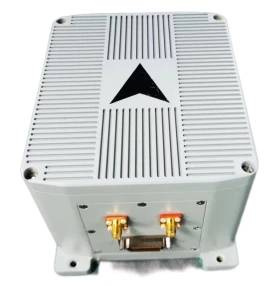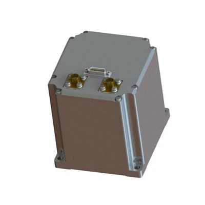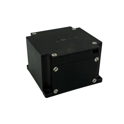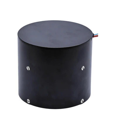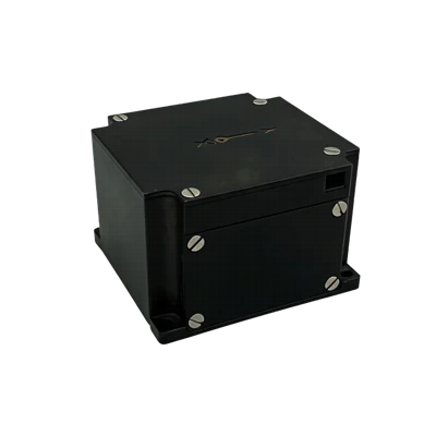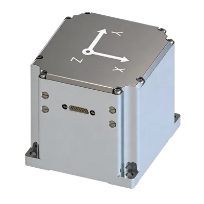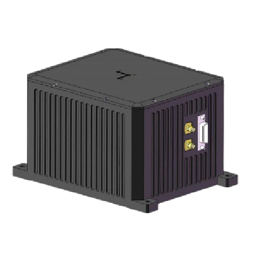
FSI400 FOG_GNSS Combined Inertial Navigation System
High-precision closed-loop fiber-optic gyroscope
Internal vibration-damping design
Long-duration autonomous navigation
Description
Main Features
- High-precision closed-loop fiber-optic gyroscope
- Internal vibration-damping design
- Long-duration autonomous navigation
- RTK high-precision navigation can be connected
- Vibration and shock resistance and electromagnetic interference resistance
- Sealed and reliable design
- Offshore differential positioning
Application Fields
- Aircraft navigation
- Attitude reference / track control for drones / vehicles / ships / boats
Product Overview
FSI400 is a highly reliable, cost-effective fiber-optic inertial/satellite integrated navigation system, widely applicable in fields such as high-precision vehicle-mounted platforms and long-endurance UAVs, as well as navigation, control, and measurement. The system uses closed-loop fiber optic gyroscopes (FOG) and high-precision accelerometers, combined with a professional GNSS board, to achieve real-time navigation output. The system output is compatible with mainstream post-processing software to obtain higher-precision navigation results and serve as a benchmark for research platforms.
Unique Technology
The system inherits the modular design philosophy of similar products and adopts high-precision silicon optical gyroscopes and high-precision MEMS accelerometers. Through multi-sensor fusion algorithm processing, the main inertial navigation data and GPS position and velocity are input into the filter, while the INS position, velocity, and attitude are also used as inputs to the filter. By comparing the difference between the two, the filter establishes an error model to estimate INS errors and uses these errors to correct the inertial navigation results, thereby obtaining integrated navigation results for velocity, position, and attitude. The inertial navigation system can provide different configuration modes to suit different carriers, such as airborne, vehicle-mounted, and shipborne.
Performance Parameters
FSI400 FOG_GNSS Combined Inertial Navigation System
|
Fiber Optic Gyroscope |
|
|
Range (°/s) |
±300 |
|
Full-temperature Bias (°/h,, 3σ) |
≤0.01 |
|
Bias Stability (°/h, 10s smoothing) |
≤0.01 |
|
Bias Instability (°/h, allan) |
≤0.001 |
|
MEMS Accelerometer |
|
|
Range (g) |
±20 |
|
Full-temperature Bias (mg,3σ) |
≤0.1 |
|
Bias Stability (μg,10ssmoothed) |
≤10 |
|
Bias Instability (μg, allan, typ) |
≤1 |
|
Navigation Accuracy |
|
|
Self-align North-seeking Accuracy (°, 1σ) |
≤0.06secL (1mil) |
|
Pure Inertial Accuracy (1σ) |
≤1 nautical mile/1 hour |
|
Electrical/Mechanical Interface |
|
|
Power Supply (V) |
18~36(ripple ≤100mV) |
|
Dimensions (mm×mm×mm) |
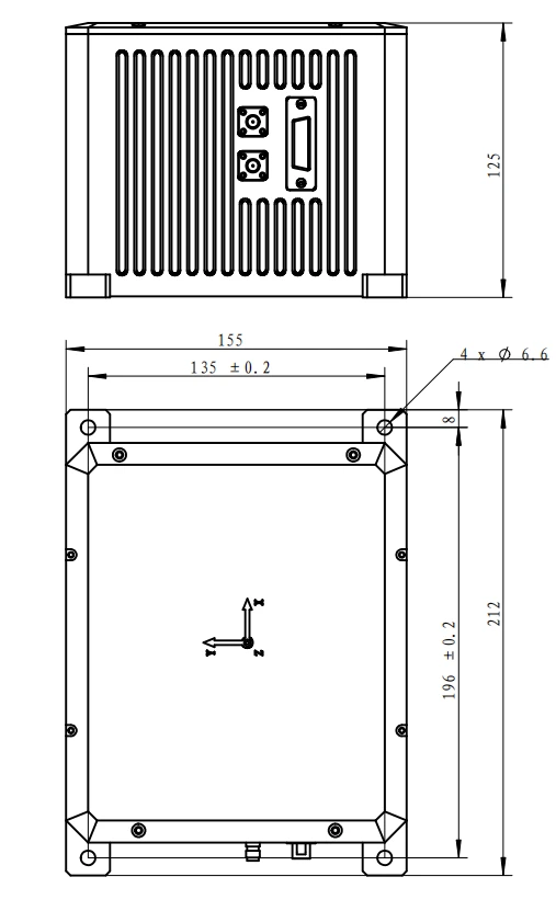
212 × 155 × 125 |
|
Weight (g) |
≤5000 |
Introduction
Overview
FSI400 uses ultra-high-precision fiber-optic gyroscopes and quartz flexure accelerometers, and is combined with a professional GNSS board. Processed by specially designed data fusion software, it can provide accurate positioning, attitude determination, and dynamic information such as three-dimensional acceleration and angular velocity. It can be widely used on scientific research platforms such as aircraft, unmanned vehicles, unmanned ships, and unmanned aerial vehicles, serving as a reference navigation system.
Features
The main features of FSI400 are as follows:
- High-precision closed-loop fiber-optic gyroscope
- Internal vibration-damping design
- Long-duration autonomous navigation
- RTK high-precision navigation can be connected
- Vibration and shock resistance and electromagnetic interference resistance
- Sealed and reliable design
- Offshore differential positioning
Composition
FSI400 mainly consists of a three-axis fiber optic gyroscope, a three-axis accelerometer, information processing circuitry, navigation software, system structural components, system test cables, and system test software.
The following outputs are provided by default:
- Three-dimensional angular velocity
- Three-dimensional acceleration
- Gyroscope temperature
- Accelerometer temperature
- Integrated navigation position, velocity, and attitude information
- Satellite receiver positioning, speed measurement, and status information
- UTC time
Application
Aircraft navigation
Attitude reference / track control for drones / vehicles / ships / boats
Product Performance
Parameters
Table1 System performance parameters
|
Fiber Optic Gyroscope |
|
|
Range (°/s) |
±300 |
|
Full-temperature Bias (°/h,, 3σ) |
≤0.01 |
|
Bias Stability (°/h, 10s avg.) |
≤0.01 |
|
Bias Instability (°/h, allan) |
≤0.001 |
|
Bias Repeatability (°/h) |
≤0.01 |
|
Angular Random Walk (°/√h) |
≤0.0005 |
|
Scale Factor Nonlinearity (ppm) |
≤10 |
|
Cross-coupling (rad) |
≤0.001 |
|
Bandwidth (Hz) |
≥200Hz |
|
MEMS Accelerometer |
|
|
Range (g) |
±20 |
|
Full-temperature Bias (mg,3σ) |
≤0.1 |
|
Bias Stability (μg,10s avg.) |
≤10 |
|
Bias Instability (μg, allan, typ) |
≤1 |
|
Bias Repeatability (ug) |
≤10 |
|
Velocity Random Walk (m/s/√h) |
≤0.01 |
|
Scale Factor Nonlinearity (ppm, ±1g) |
≤100 |
|
Cross-coupling (rad) |
≤0.001 |
|
Bandwidth (Hz) |
≥200Hz |
|
Navigation Accuracy |
|
|
Self-alignment North-seeking Accuracy (°, 1σ) |
≤0.06secL (1mil) |
|
Pure Inertial Accuracy (1σ) |
≤1 nautical mile/1 hour |
|
Depth Measurement Accuracy (cm) |
≤5(marine environment) |
|
Combination Horizontal Position (m,1σ) |
≤2(single point) |
|
Combination Vertical Position (m,1σ) |
≤3(single point), |
|
Combination Horizontal Velocity (m/s,1σ) |
≤0.05 |
|
Combination Vertical Velocity (m/s,1σ) |
≤0.1 |
|
Combination Heading (°,1σ)) |
≤0.1(dynamic) |
|
Combination Horizontal Attitude (°,1σ) |
≤0.008(single point, dynamic) |
|
Electrical/Mechanical Interface |
|
|
Power Supply (V) |
18~36(ripple ≤100mV) |
|
Steady-state Power (W) |
≤18 |
|
Startup Time (s) |
≤2 |
|
Communication Interface |
RS422/RS232 |
|
Update Rate (Hz) |
200 |
|
Dimensions (mm×mm×mm) |
212 × 155 × 125 |
|
Weight (g) |
≤5000 |
|
Operating Environment |
|
|
Operating Temperature (°C) |
-40 ~ +70 |
|
Storage Temperature (°C) |
-55 to +85 |
|
Vibration (g, Rms) |
20~2000HZ, 6.06 |
|
Shock (g) |
100g/1ms |
|
Reliability |
|
|
MTBF (h) |
20000 |
Electrical Characteristics
The product's external connector plug uses sealed J29A-25Zk connector; the pin definitions are as follows:
Table1Pin Definition of FSI400
|
J29A-25Zk pin number |
Connector definition |
Remarks |
|
1,2 |
+ (9~36) COME |
Power supply positive |
|
3,4 |
+(9~36)VGND |
|
|
5 |
INS_RS422_1_TX+ |
M1Channel RS422interface (configuration, upgrade, output) |
|
6 |
INS_RS422_1_TX- |
|
|
7 |
INS_RS422_1_RX+ |
|
|
8 |
INS_RS422_1_RX- |
|
|
9 |
DGND |
|
|
10 |
INS_RS422_2_TX+ |
M2Channel RS422interface outputs IMUprotocol (55AC) |
|
11 |
INS_RS422_2_TX- |
|
|
12 |
INS_RS422_2_RX+ |
|
|
13 |
INS_RS422_2_RX- |
|
|
14 |
DGND |
|
|
15 |
GPS_RS232_TXD |
M4Channel RS232interface Directly connected to the GNSS board card Output GNSS raw observations |
|
16 |
GPS_RS232_RXD |
|
|
17 |
DGND |
|
|
18 |
TTL_IN+ |
External satellite receiver mode PPS signal input |
|
20 |
DGND |
|
|
21 |
INS_RS422_3_TX+ |
M3Channel RS422interface Real-time integrated navigation output |
|
22 |
INS_RS422_3_TX- |
|
|
23 |
INS_RS422_3_RX+ |
|
|
24 |
INS_RS422_3_RX- |
|
|
25 |
DGND |
After the power supply voltage drops below the device operating threshold voltage, the power-off hold time tOFF before powering on again must not be less than 3s; an insufficient power-off interval may cause abnormal device startup, latch-up, or initialization failure.
External Communication
FSI400 is defined in the wiring diagram above, there are 3 channels of RS422output, 1 channel ofRS232output, and one channel of PPS in.
M1Channel Output
The M1channel is the main configuration port of the device, an RS422communication interface, with functions such as configuration, software upgrade, and output configuration protocol; it can be configured to output other protocols. The output protocol currently configured for this channel is the standard IMU protocol.
The general IMU protocol outputs IMU data by default in timed broadcast mode, with a default output frequency of200Hz; each frame of data 40bytes, baud rate 460800bps,1bit start bit,8data bits,1stop bits, no parity. For multi-byte variables, the low byte is sent first, then the high byte.
Table1GeneralIMUProtocol
|
No. |
Byte Start Index |
Number of Bytes |
Content |
Equivalent |
Range |
Unit |
Remarks |
|
1 |
0 |
1 |
0x55 |
1 |
Frame header |
||
|
2 |
1 |
1 |
0xAA |
1 |
Frame header |
||
|
3 |
2 |
1 |
36 |
1 |
Data length |
||
|
4 |
3 |
4 |
PCnum |
1 |
1 ms count value |
||
|
5 |
7 |
4 |
Angular rate X |
0.000001 |
[-2000,2000] |
°/s |
|
|
6 |
11 |
4 |
Angular rateY |
0.000001 |
[-2000,2000] |
°/s |
|
|
7 |
15 |
4 |
Angular rateZ |
0.000001 |
[-2000,2000] |
°/s |
|
|
8 |
19 |
4 |
AccelerationX |
0.000001 |
[-40,40] |
m/s2 |
|
|
9 |
23 |
4 |
AccelerationY |
0.000001 |
[-40,40] |
m/s2 |
|
|
10 |
27 |
4 |
AccelerationZ |
0.000001 |
[-40,40] |
m/s2 |
|
|
11 |
31 |
2 |
System temperature |
0.008 |
[-120,120] |
℃ |
|
|
12 |
33 |
2 |
Year, month, day |
- |
- |
- |
Bit0~bit4: day 0-31 Bit5~bit8: month 0~12 Bit9~bit15: year 0~99 For example1100011110011111 represents2099year12month31day |
|
13 |
35 |
4 |
timestamp |
0.1 |
- |
ms |
(h*3600+m*60+s)*10000 Example:0011 0011 0111 1111 1001 0111 1111 1111 Represents:23h59min59.9999s |
|
14 |
39 |
1 |
Checksum |
1 |
[0,255] |
subscript (2~38) low-order byte of the byte cumulative sum8bit |
M2 channel output
M2This channel is the output port of the second channel, with no configuration or upgrade function, and outputs the M PV4_IMU protocol. The protocol is as follows
Table 2 IMU data format table
|
Bytes |
Format |
Description |
|
0 |
U8 |
Header 0x55 |
|
1 |
U8 |
Header 0xAC |
|
2~3 |
U16 |
GPS Week |
|
4~11 |
double |
m-second |
|
12~15 |
float |
Gyro X, deg/s |
|
16~19 |
float |
Gyro Y, deg/s |
|
20~23 |
float |
Gyro Z, deg/s |
|
24~27 |
float |
ACC X, m/s2 |
|
28~31 |
float |
Founded j, m/bad |
|
32~35 |
float |
Founded g, m/bad |
|
36~37 |
U16 |
ODO count |
|
38~39 |
U16 |
CAN BUS DATA,0.01m/s |
|
40~41 |
I16 |
Temperature, 0.5/LSB |
|
42 |
U8 |
IMU status |
|
43 |
U8 |
Checksum, unsigned char adding from Byte2~Byte42 |
|
115200-8-N-1, little-endian, output rate: 200Hz |
||
Note:
IMU status
Bit1 PPS Normal0 Error 1 – When PPS has a trailing 0, the subsequent one will not skip1.
Bit2 TIME (sow) Normal0 Error1 When SOW has a trailing value0, subsequent values will not jump1.
Bit3 IMU1 Normal0 Error1
Bit4 IMU2 error (if have) Normal0 Error1
Bit5 ODONormal0 Error1
Bit6 CAN Normal0 Error1
Bit7~8 static status 0 1 2 3 Stationary0 Slight1 Moderate2 Severe 3
The coordinate system is right-front-up, representing angular rate of change and acceleration. After decoding, it becomes front-right-down, and also becomes radian increments and velocity increments.
When there are no satellites at startup GPS-WEEKis0, m-second starts from0the beginning and increases, with the data propagated.
After the satellites are valid, GPS-WEEK and m-second only need to be synchronized with the board card.
M3 channel output
The M3 channel is the third-channel output port, with no configuration or upgrade function, and outputs the real-time integrated navigation protocol. The real-time integrated navigation protocol outputs data by default in a timed broadcast manner, with 164 bytes per frame, an output frequency of 200Hz, a baud rate of 460800bps, 1 start bit, 8 data bits, 1 stop bit, and no parity. For multi-byte variables, the low byte is sent first and then the high byte. A typical communication protocol is shown in Table 3.
Table3Autonomous Driving Positioning Terminal Communication Protocol
|
No. |
First Byte Order |
Number of Bytes |
Signal Name |
Measurement Unit or Content |
Equivalent |
Interface Accuracy Description |
|
1 |
0 |
1 |
Frame Header 1 |
Content: 55H |
1 |
8-bit unsigned integer |
|
2 |
1 |
1 |
Frame Header 2 |
Content: AAH |
1 |
8-bit unsigned integer |
|
3 |
2 |
1 |
Data length |
Content: 160H |
1 |
8-bit unsigned integer |
|
4 |
3 |
4 |
PCNum |
- |
1 |
Unsigned 16-bit integer |
|
5 |
7 |
1 |
System status word |
- |
1 |
Self-test error: 0x1F; greater than 0x41 indicates a user-available state (integrated navigation state) |
|
6 |
8 |
1 |
Real-time status word |
- |
1 |
Telemetry backup |
|
7 |
9 |
2 |
Device status word |
- |
1 |
Telemetry backup |
|
8 |
11 |
4 |
Process status word |
- |
1 |
Telemetry backup |
|
9 |
15 |
4 |
X gyroscope angular velocity |
[-500,500]°/s, |
0.0000005 |
Transient value |
|
10 |
19 |
4 |
Y-axis gyroscope angular velocity |
[-500,500]°/s, |
0.0000005 |
Transient value |
|
11 |
23 |
4 |
Z-axis gyroscope angular velocity |
[-500,500]°/s, |
0.0000005 |
Transient value |
|
12 |
27 |
4 |
X-axis acceleration |
[-80m/s2,80m/s2] |
0.000001 |
Transient value |
|
13 |
31 |
4 |
Y-axis acceleration |
[-80m/s2,80m/s2] |
0.000001 |
Transient value |
|
14 |
35 |
4 |
Z-axis acceleration |
[-80m/s2,80m/s2] |
0.000001 |
Transient value |
|
15 |
39 |
4 |
Combined longitude |
[-180,180]deg |
0.0000001 |
|
|
16 |
43 |
4 |
Integrated latitude |
[-90,90]deg |
0.0000001 |
|
|
17 |
47 |
4 |
Integrated altitude |
[-1000,16384]m |
0.00001 |
|
|
18 |
51 |
2 |
Integrated north velocity |
[-300,300]m/s |
0.005 |
|
|
19 |
53 |
2 |
Integrated vertical velocity |
[-300,300]m/s |
0.005 |
|
|
20 |
55 |
2 |
Integrated east velocity |
[-300,300]m/s |
0.005 |
|
|
21 |
57 |
2 |
Roll angle |
[-180,180]deg |
0.006 |
|
|
22 |
59 |
2 |
Heading angle |
[0,360]deg |
0.006 |
Unsigned 16-bit integer, positive starting east of north |
|
23 |
61 |
2 |
Pitch angle |
[-90,90]deg |
0.006 |
|
|
24 |
63 |
4 |
Receiver longitude |
[-180,180]deg |
0.0000001 |
|
|
25 |
67 |
4 |
Receiver latitude |
[-90,90]deg |
0.0000001 |
|
|
26 |
71 |
4 |
Receiver altitude |
[-1000,16384] m |
0.00001 |
|
|
27 |
75 |
2 |
Receiver north velocity |
[-300,300]m/s |
0.005 |
|
|
28 |
77 |
2 |
Receiver vertical velocity |
[-300,300]m/s |
0.005 |
|
|
29 |
79 |
2 |
Receiver east velocity |
[-300,300]m/s |
0.005 |
|
|
30 |
81 |
1 |
Temperature |
℃ |
1 |
|
|
31 |
82 |
1 |
Receiver positioning status |
- |
1 |
bit0-3: Original receiver positioning flag; bit4-7: directional signal. |
|
32 |
83 |
4 |
Seconds of day |
s |
0.001 |
|
|
33 |
87 |
1 |
year |
1 |
||
|
34 |
88 |
1 |
month |
1 |
||
|
35 |
89 |
1 |
day |
1 |
||
|
36 |
90 |
1 |
Number of positioning satellites |
1 |
||
|
37 |
91 |
2 |
Track angle |
[0.360]deg |
0.006 |
Unsigned 16-bit integer, positive starting east of north |
|
38 |
93 |
2 |
Dual-antenna heading |
[0.360]deg |
0.006 |
Unsigned 16-bit integer, positive starting east of north |
|
39 |
95 |
2 |
Backup Information 1 |
- |
1 |
|
|
40 |
97 |
2 |
Backup Information 2 |
- |
1 |
|
|
41 |
99 |
2 |
Backup Information 3 |
- |
1 |
|
|
42 |
101 |
2 |
Backup Information 4 |
- |
1 |
|
|
43 |
103 |
2 |
Backup Information 5 |
- |
1 |
|
|
44 |
105 |
2 |
Number of Orientation Satellites |
- |
1 |
|
|
45 |
107 |
1 |
Backup Information 6 |
- |
1 |
|
|
46 |
108 |
1 |
Backup Information 7 |
- |
1 |
|
|
47 |
109 |
1 |
Backup Information 8 |
- |
1 |
|
|
48 |
110 |
1 |
Backup Information 9 |
- |
1 |
|
|
49 |
111 |
4 |
100 mega second count |
- |
1 |
Unsigned 16-bit integer |
|
50 |
115 |
4 |
Backup Information 10 |
- |
1 |
|
|
51 |
119 |
4 |
Backup Information 11 |
- |
1 |
|
|
52 |
123 |
4 |
Backup Information 12 |
- |
1 |
|
|
53 |
127 |
4 |
Backup Information 13 |
- |
1 |
|
|
54 |
131 |
4 |
Backup Information 14 |
- |
1 |
|
|
55 |
135 |
4 |
Backup Information 15 |
- |
1 |
|
|
56 |
139 |
4 |
Backup Information 16 |
- |
1 |
|
|
57 |
143 |
4 |
Backup Information 17 |
- |
1 |
|
|
58 |
147 |
4 |
Backup Information 18 |
- |
1 |
|
|
59 |
151 |
4 |
Backup Information 19 |
s |
1 |
|
|
60 |
155 |
4 |
Backup information 20 |
s |
1 |
|
|
61 |
159 |
4 |
Backup information 21 |
- |
1 |
|
|
62 |
163 |
1 |
Checksum |
Data length and the low 8 bits of the byte sum of the data |
1 |
M 4-Channel Output
M4The channel is the GNSS board direct-connection output port, RS232 output, output baud rate is460800. The current output protocol is the Unicore board protocol. The output format is configured as follows:
<GPGGA COM1 1
<GLOEPHEMB COM1 260
<GALEPHEMB COM1 270
<BD2EPHEMB COM1 290
<GPSEPHEMB COM1 300
RANGECMPB COM1 1
Outputs 1 s of raw observation values in binary compressed format. Outputs binary ephemeris data, including GPS, BDS, GLA, and GLO. The baud rate is 460800.
Real-time Navigation Working Mode
a) Power-on self-test
After the product is powered on, it performs a self-test. The self-test time is no more than15s. If the self-test fails, the process terminates. If the self-test succeeds, it enters standby mode.
b) Standby
The standby time is no more than 10s. If valid satellite information is available during standby, the satellite information is acquired and the system enters alignment. If the satellite information is invalid, the position information stored in flash is used to enter alignment.
c) Alignment
The alignment time is no greater than 300s. During the alignment process, the carrier is required to remain stationary. After alignment is completed, it automatically enters the navigation state.
d) Navigation
During the navigation phase, when GNSS is valid, the inertial navigation system and GNSS RTK perform integrated navigation. When GNSS is invalid, the inertial navigation system performs autonomous navigation.
Structure
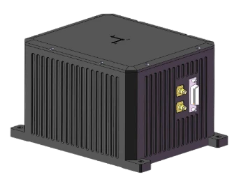
The system adopts an aluminum alloy structure, is lightweight, and has very high structural strength, with resistance to vibration and shock.
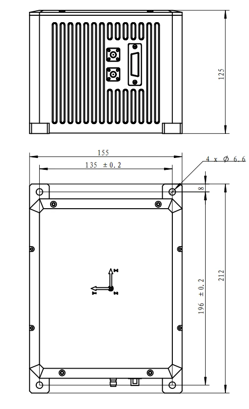
Figure1SystemOverall Structural Dimensions
Hot Tags: fsi400 fog_gnss combined inertial navigation system, China fsi400 fog_gnss combined inertial navigation system manufacturers, factory