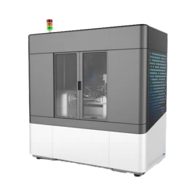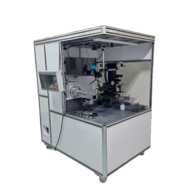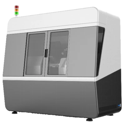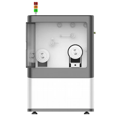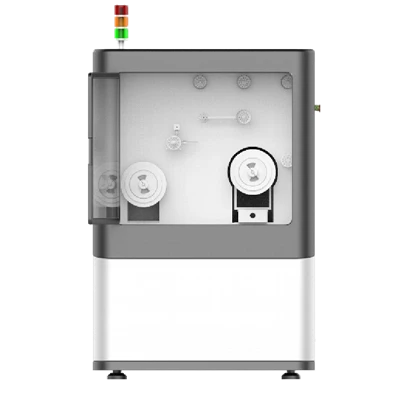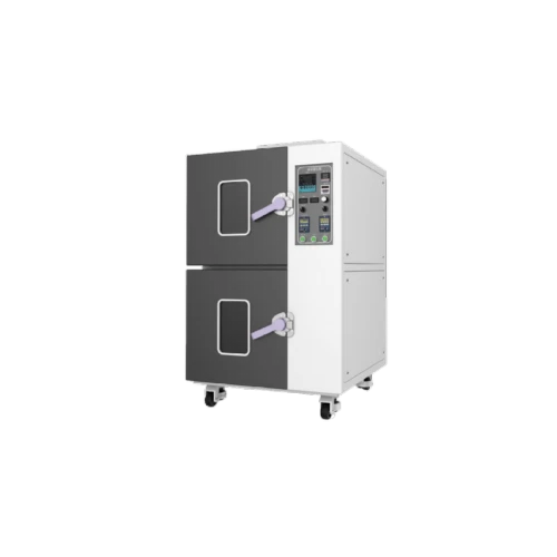
UV02 Rotary UV Curing Chamber
Adjustable UV intensity
Adjustable curing temperature
Rotary product curing
Description
Key Features
- Adjustable UV intensity
- Adjustable curing temperature
- Rotary product curing
- Adjustable light distance
Applications
- Fiber coil
- Other curing applications
Product Introduction
Company's UV02 UV curing chamber is primarily used to cure finished fiber coils, where UV light fixes the adhesive to the fiber and bobbin. The equipment lets operators set both the UV intensity and the curing temperature, enabling the entire curing cycle to be carried out under stable, constant conditions for consistent bond quality.
Unique Technology
Company is a high-tech enterprise with full closed-loop capabilities from fiber winding equipment and coils to FOGs, fiber/MEMS inertial products, IMU circuits, software, and test equipment. End-to-end process control improves quality and reduces costs. Operating under ISO9001 with strict processes, it ensures product reliability and consistency.
Parameters
UV02 Rotary UV Curing Chamber Specifications
|
Parameter |
Specifications |
|
Heating Chamber System: performance indicators tested with UV illumination off |
|
|
Power Supply Voltage (V,Hz) |
220 50 |
|
Chamber Dimensions(W×D×H mm) |
500*400*500 |
|
Rated Power (W) |
2000 |
|
Temperature Fluctuation (℃) |
±1 |
|
Temperature Range (℃) |
Room temp. +10–200(adjustable), 60–200 under UV(adjustable) |
|
Heating Rate (℃/min) |
Avg. 1–5 (adjustable) |
|
UV Illumination System: consists of UV lamp, reflector, adjustable power supply, and exhaust system |
|
|
UV Lamp Type |
Air-cooled high-pressure mercury lamp |
|
UV Lamp Quantity (pcs) |
1 |
|
UV Lamp Rated Power (W) |
1000 |
|
UV Peak Wavelength (nm) |
365 |
|
Exhaust Fan Power (W) |
150 |
|
Lamp Length (mm) |
165, luminous zone 50 |
|
Lamp Housing Dimensions (mm) |
Width 150, height 105, length customized to lamp |
|
Lamp Housing Material |
Aluminum, dual reflectors, filter quartz glass below |
|
Time Control |
0–999 (H, M, S) (continuous/interval freely configurable) |
|
Product Rotation System: consists of rotary motor and stepless speed controller |
|
|
Motor Power (W) |
100 |
|
Motor Speed (r/min) |
1~20 (adjustable, speed range selectable) |
|
Motor Shaft Dimensions (mm) |
50 × M12 internal thread |
|
Rotation Shafts (pcs) |
1 (custom) |
|
Speed Controller |
Digital stepless speed controller |
|
Irradiance Control |
|
|
Adjustable Lamp-to-Shaft Distance (mm) |
100–350 (achieved by adjusting lamp height) |
|
Irradiance Reference Tables (lamp vs. shaft distance) × 2 |
One each for 1000 W and 500 W lamps |
Introduction
UV02 is mainly used to solidify the optical fiber coil, and fix the glue, optical fiber and framework through ultraviolet light.
Technical Data
Heating system
Various performance indicators are normal when operate without opening the UV system.
Power supply: 220V 50HZ
Volume: 500*400*500(width * depth * height mm)
Rated power: 2000W
Temperature fluctuation:±1℃
Temperature range:room temperature +10℃-200℃(adjustable),under exposure 60℃-200℃(adjustable)
Heating rate: 1~5℃/min, average(adjustable)
Ultraviolet System
Consists of an ultraviolet lamp, a reflective lampshade, a dimmable power supply and an exhaust system.
UV lamp type:Air cooled high-pressure mercury lamp
UV lamp quantity: 2
Rated power of UV lamp: 1000W / piece
UV peak wavelength: 365nm
Exhaust motor power: 150W
Lamp tube length: 165mm, Luminous area: 50mm
Lampshade size:width 150mm, height 105mm, the lampshade length is customized according to the length of the lamp
Lampshade material: aluminum, two reflectors, with filter quartz glass below
UV exposure time control:0~999(H,M,S)(Any continuous gap can be set)
Rotation System
Consists of rotating motor and stepless governor
Motor power: 100W each
Motor speed:1r~20r/min(Adjustable, rotation speed range optional)
Motor shaft length:50mm*M12, internal thread
Rotation axis:1, customized
Governor: digital display stepless governor
UV Exposure Control
Adjustable distance between lamp tube and rotation axis:100mm~350mm(By adjusting the lamp height)
Two irradiance cross-reference tables (between lamp and rotation axis), one 1000W lamp tube and one 500W lamp tube
Equipment Composition
Heating system
UV system
Rotation system
Note: please refer to the technical appendix of the equipment sales contract for the specific content of the equipment composition. The indicators mentioned in this manual are within the scope of the equipment sales contract.
Installation
The floor for equipment installation shall be flat.
Only qualified electrical personnel who are familiar with the electrical schematic connection diagram of the equipment in advance can carry out the electrical wiring installation of the equipment.
The internal wiring of the equipment has been completed before delivery. Please check the wiring carefully before normal operation. In the process of transportation, it is necessary to prevent the joint from loosening due to the bumping of vehicles, which will cause the equipment to fail to work normally.
Requirements for Installation
In order to ensure the production of qualified products and extend the service life of all parts of the equipment, the user's workshop needs to meet the following conditions:
Power Supply
Single phase three wire system: single phase three wire 220V (± 10%), 50Hz, 2.0kw
Users need to provide good grounding conditions for the equipment (independent grounding device shall be designed according to the requirements of international standards to protect personnel and eliminate electromagnetic interference to a certain extent).
Installation Environment
Temperature:0-30℃
Dust free environment
Relative humidity in the range of 20-90% (no condensation)
No corrosive gas and combustible gas
A well-ventilated place is conducive to the heat dissipation of the equipment
Safety Instructions
Please read the following content carefully to ensure personal safety before using this equipment for the first time!!!
 Warning!
Some parts of the equipment have dangerous voltage and rotating action during operation.
Failure to pay attention to safe operation may cause serious personal injury or property loss.
Only qualified personnel who have a thorough understanding of the following warnings, precautions and maintenance procedures can operate the equipment or work around it.
The key of using this equipment safely to produce qualified products lies in correct operation and maintenance process.
Qualified personnel:
It refers to the operation and maintenance personnel who are familiar with the equipment, and must have the following qualifications:
According to the safety regulations, the personnel who have obtained the corresponding qualification in the aspects of power supply, power-off, cleaning, grounding, marking of circuits and electrical equipment shall be trained.
Personnel trained in proper maintenance and use of protective equipment in accordance with safety regulations.
Personnel trained in first aid.
 DANGER!
It refers to the death, serious personal injury or material property damage that may be caused if the correct preventive measures are not taken.
 ATTENTION!
It refers to the relevant parts in the relevant product information and manual that should be highly valued.
Maintenance Precautions
Only qualified personnel who are familiar with the equipment and attached datasheet are allowed to operate or repair the equipment.
During normal operation, all panels and doors of the equipment must be closed. It is forbidden to touch all production parts by hand at will to avoid personal injury.
Before visual inspection and maintenance work, ensure to cut off the AC power supply; before cutting off the AC power supply, the controller and motor may have dangerous voltage, even when the controller contactor is disconnected, there is still dangerous voltage, so it is necessary to release the charge before operation (the best way is to leave it for a period of time after power off and wait for the charge to be released).
During live measurement, live wiring shall not be touched under any conditions.
Ensure good grounding conditions and safe operation of the equipment; due to the use of many controllers and other components, the equipment may have high induced voltage, so it is necessary to ensure safe grounding.
When working on live parts, it is necessary to stand on the insulating surface, that is, to ensure that there is no direct contact with the ground.
After the equipment is powered on, the untrained and unqualified personnel shall not touch the electrical components and wiring terminals at will, so as to avoid personal injury; in case of wire disconnection, please power off before handling.
Carefully following the relevant instructions and observe the "danger" and "warning" precautions.
When cleaning the equipment, please turn off the power, do not wipe it with electricity, and do not wash it with water.
Please operate in strict accordance with the operation steps of the equipment to ensure the production of qualified products; for other maintenance precautions, please contact us.
Equipment Operation
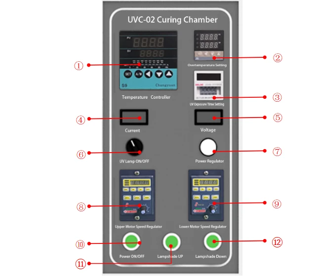
Operation Process
No.1 is a temperature controller of the upper chamber. This temperature controller can set different temperatures and different times, and has memory function, which can automatically memorize the last set temperature program. The overtemperature setting of controllers is originally set as 3 ℃, when the SV temperature on the instrument is 3 ℃ higher than the PV temperature, the temperature controller will automatically cut off the power supply of heating and internal circulation fan. When the temperature drops, the power supply of heating and internal circulation fan will turn on, and enter the normal heating state. Due to the curing characteristics of optical fiber and glue, it is recommended that the maximum temperature set by the temperature controller shall not be over 45 ℃. Before operating this temperature controller, please check the manual of the temperature controller. (If there is no need for heating function during UV curing, the lower the temperature is the better, then the program of temperature controller doesn't need to be started during normal operation.)
No. 2 is the secondary temperature protection controller in the upper chamber. Its principle is similar to that of No. 1. If the overtemperature protection of No. 1 fails or the device fails, No. 2 will be started as the secondary protection device, and the heating will be cut off. At the same time, the exhaust fan on the back of the equipment will be started, and the hot air in the chamber will be pumped out, cooling the chamber quickly. The overtemperature protection value of this temperature controller is recommended to be set between 50 ℃ and 55 ℃. Before operating the controller, be sure to check the manual of it.
No. 3 is the time controller of UV exposure. The setting mode of the time controller is different from that of the temperature controller. It needs to set the time when the device is not started (that is, set the UV exposure time before pressing the power switch No. 11). It is invalid to set the time after the time controller is powered on. The maximum value of time relay can be set to 999 hours, in which S is seconds, M is minutes, H is hours, the + is the increase key, and the - is the decrease key. If you need to set exposure for 48 hours, the time relay should be set as: 048H; if you need exposure for 52 minutes, set to 052M; exposure 240 hours, set to 240H. and so on.
No. 4 is the real-time current of the UV lamp when it is on. The current displayed on the current monitor multiplied by the voltage displayed on the No. 5 voltage monitor is equal to the present power of the UV lamp. Each time the lamp is cold started, the value on the current monitor will change according to the temperature around the lamp. When the temperature in the lampshade rises to 130-160 degrees, the current will be stable.
No. 5 is a real-time voltmeter when the UV lamp is lit. The voltage shown on the voltmeter multiplied by the current shown on ammeter No. 4 equals the current power of the lamp light. The value on the voltmeter will change according to the temperature around the lamp each time the lamp is cold-started, and the voltage will stabilize at a value when the temperature inside the lampshade rises to 130 degrees~160 degrees.
No. 6 is the power adjustment knob of the lamp, and this adjustment knob is not recommended to screw to the right end, that is, the maximum use. Ammeter and voltmeter of UV lamp display values stabilized at a value (the display of the current and voltage fluctuations of no more than 10 can be considered stable), you can twist the knob to adjust the power of the lamp, observe the values on the ammeter and voltmeter while twisting, when they multiply the value equal to the required power, stop twisting. (You can also put an irradiometer in the chamber to measure the real-time irradiance, observe the irradiance while twisting the knob, until the irradiance reaches the required curing irradiance.)
Note: Because the lamp power adjustment is extremely sensitive, so the knob must be twisted slowly, by observing the ammeter voltmeter, or irradiance meter. (After adjusting the knob for the first time, remember the scale on the knob corresponds to the value on the dial, and you don't need to adjust the knob when you use it later).
No. 7 is the function select knob of the UV lamp, before starting the lamp normally, this knob should be screwed to WORK. If you need to replace the fiber coil in the middle of UV curing, then you can screw this knob to STANDBY, the lamp will be dimmed and enter the low power state. After finish replacing fiber coil, screw the knob to WORK. If this UV curing box is only used in the standard curing test of the fiber coil, it is not recommended to screw the knob to STANDBY, and it is not recommended to open the chamber in the middle of the operation.
No. 8 is the ON and OFF knob of the UV lamp. After placing the fiber coil, press the No. 11 power switch, and then adjust the knob to 'ON' mode, and the lamp will be on. If it is necessary to turn off the lamp when exposure, adjust the knob directly to 'OFF' mode, it is not recommended to turn off the No. 11 power switch directly. (After the lamp stops working, there is also a high temperature on the surface of the lamp and in the lamp shade, when the lamp goes out after the curing, and the fan of the lamp will still work for 120 seconds, dissipating heat of lampshade interior.)
No. 9 is the speed regulator of the rotating spindle in the upper chamber. Functions including startup, stop, forward rotate, reverse rotate, automatic rotate after startup, or rotate only after pressing the direction button.
FWD: forward rotating
REV: reverse rotating
STOP: stop rotating
Black knob: rotation speed adjustment of rotation axis,
MODE: menu
↑: increase
↓: decrease
ENTER: confirm
On the LCD screen of the regulator, the current real-time speed of the rotation shaft and the current direction of the rotation shaft are displayed. In each UV curing test, just press REV or FWD to start the rotation shaft.
No. 10 is the speed regulator of the rotating spindle in the lower chamber (room temperature curing), which operates in the same way as No. 9 governor.
No. 11 is the power button of UV curing chamber. After setting the exposure time, placing the fiber coil, and closing the chamber door, you can press the power button. When the button is pressed, the green panel is concave and the light green is on. Press it again, the green panel will be flat and the green light will be off, then the power supply will be disconnected.
No.12 is the button to control the rising of the lampshade. Specific operation: press the No.11 power button, open the door of the UV curing chamber, observe the stainless-steel strip on the lampshade and the stainless-steel ruler on the left side, press or click No.12 and No.13 button, the lampshade will rise or fall, and release the button when the distance between the lampshade and the rotating spindle meets requirement. (If the distance is far, press and hold the button. When make tiny movement, click the button quickly to adjust the lampshade.)
No. 13 is the button to control the lowering of the lampshade. The operation mode is the same as that of No. 11.
Hot Tags: uv02 rotary uv curing chamber, China uv02 rotary uv curing chamber manufacturers, factory