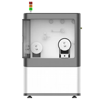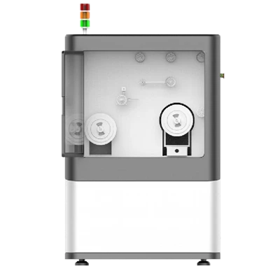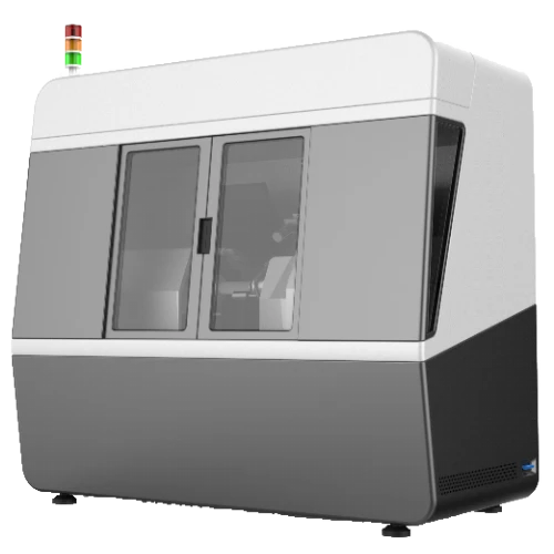
RH04 Fiber Coil Winding Machine
Tool-free spool change, easy operation
Precision assembly, stable operation
Uniform tension, stable winding
Description
Key Features
- Tool-free spool change, easy operation
- Precision assembly, stable operation
- Uniform tension, stable winding
- PLC-controlled, easy monitoring
- Collision protection, auto-stop
Applications
- Winding fiber coils
Product Introduction
Company's RH04 fiber coil winding machine features high automation, high-precision tension control, and easy operation, and is especially suited to the four-pole symmetric winding method for FOG coils. It uses a PLC coordinated with servo motors to achieve precise positioning and control of the winding process. An external HMI display enables command input and key-parameter readout for real-time process monitoring. A CCD camera is also added for online microscopic observation of the winding, allowing irregularities to be detected and corrected promptly.
Unique Technology
Company is a high-tech enterprise with full closed-loop capabilities from fiber winding equipment and coils to FOGs, fiber/MEMS inertial products, IMU circuits, software, and test equipment. End-to-end process control improves quality and reduces costs. Operating under ISO9001 with strict processes, it ensures product reliability and consistency.
Parameters
RH04 Fiber Coil Winding Machine Specifications
|
Parameter |
Specifications |
|
Fiber Diameter Range (mm) |
Φ0.1~Φ0.26 |
|
Winding Speed (r/min) |
40 |
|
Maximum Tooling Diameter (mm) |
250 |
|
Tension Control Range (g) |
5-50 |
|
Tension Precision (g) |
±0.5(20r/min) |
|
Traverse Stroke (Coil Width) (mm) |
0-60 |
|
Counting Accuracy (turns) |
0.1 |
|
Displayable Parameters |
Turns, Tension, Length, Layer Count, Spindle Direction, Traverse Direction, Coordinate, Speed, real-time display of wound length for current layer |
|
Programmable Parameters |
Fiber Diameter, Spindle Direction, Traverse Direction, Speed, Tension, Spool Diameter, Spool Width, etc. |
|
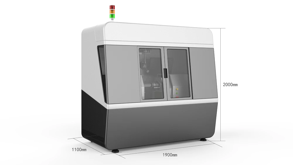
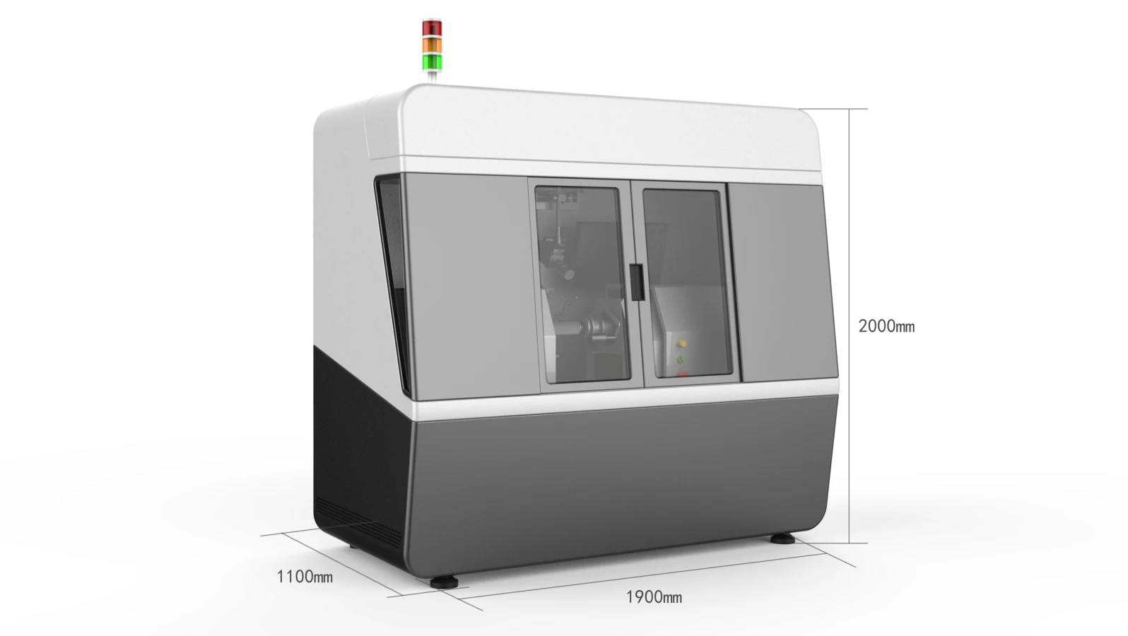
Equipment Dimensions (mm) |
L 1900 × W 1100 × H 2000 |
Outline Drawing
Safety Notice
Before using the equipment, please carefully read the following safety section in order to ensure personal safety!!!!
WARNING
- The power supply of this equipment is two-phase, three-wire 220V, pay attention to high voltage.
- This equipment operates with rotating parts.
- Failure to observe safe instructions may cause serious personal injury or property damage.
- Only qualified personnel who thoroughly understand the following warnings, precautions and maintenance procedures should operate this equipment.
- The key to safely using this equipment to produce qualified products lies in the proper mastery of the operation and maintenance process.
QUALIFIED PERSONNEL
Refers to people familiar with the operation and maintenance of this equipment and must have the following qualifications.
- Trained and qualified in power supply, disconnection, cleaning, grounding, and marking of wiring and electrical equipment as required by safety regulations.
- Trained in the proper maintenance and use of equipment as defined by safety regulations.
- Trained in emergency care.
DANGER
Refers to death, serious injury or property damage that would have resulted if proper precautions had not been taken.
ATTENTION
Refers to the relevant parts of the product information and manuals that should be given high priority.
NOTES
- Only qualified personnel familiar with this equipment and the information supplied with it are permitted to operate or service the equipment.
- In the normal operation of the equipment, it is prohibited to touch the various production parts with your hands at will to prevent personal injury; to prevent damage to the machine.
- Before performing intuitive overhaul and maintenance work, make sure that the AC power is disconnected; both the controller and the motor may carry dangerous voltages until the AC power is disconnected.
- In the charged measurement, regardless of the circumstances are not allowed to touch the charged wiring; instrumentation measurement gear should be correct, to avoid incorrect gear and cause damage to the equipment phenomenon occurs.
- Ensure that the equipment is well grounded and safe to operate.
- After the equipment is energized, personnel without training, do not touch the various electrical components, terminals, etc., so as not to cause personal injury; such as the occurrence of line connection off phenomenon, please disconnect the power before processing.
- When cleaning and maintaining the equipment, please turn off the power to carry out, do not operate with electricity, is strictly prohibited to clean with water.
- Please strictly follow the equipment operation steps to ensure the production of qualified products; on maintenance of other notes, please contact us.
Requirements for Environment
In order to ensure the production of qualified products, and at the same time to extend the service life of the various components of the equipment, the user plant needs to have the following conditions:
Supply Voltage
Two-phase three-wire system 2×220V±10%, 50HZ±2% 3.5KW
Good grounding conditions must be provided (separate grounding device in accordance with international standards for personal protection and some degree of elimination of electromagnetic interference). With leakage and anti-static grounding.
Installation Environment
Temperature 20~25℃
Relative humidity 30 to 80% (no condensation)
Dust-free environment, cleanliness 100,000 grade
No corrosive or flammable gases
Well-ventilated premises, for hot air dissipation and personnel ventilation
No electromagnetic interference or harmful rays
Workshop illumination meets the requirements of precision instruments
The ground should be flat, bearing 500Kg / m2
Application and Characteristics of The Equipment
RH04 fiber coil winding machine has the characteristics of high automation, high tension precision control, and easy to operate, and it is suitable for the quadrupole symmetrical winding method of FOG coils.
RH04 fiber coil winding machine adopts PLC and high precision servo motor to complete the precise positioning and control of itself. Through a touch screen which can be used for human-computer interaction, the input of operation instructions and the display of key parameters are realized, so as to facilitate the real-time monitoring of winding process. At the same time, a CCD device is added to observe the fiber winding process online, so as to find out the irregular phenomenon in the winding process and correct it in time. Under the principle of strengthening product quality supervision and ensuring winding requirements, four technical points can be summarized as follows:
1) Automatic precise fiber arrangement. The PLC module calculates the fiber arrangement position automatically according to the winding speed and fiber diameter, and controls the fiber guide wheel to track and locate the fiber arrangement position automatically. The fiber arrangement accuracy can reach 0.005mm.
2) High precision tension control. The high-resolution tension sensor is adopted to feed back the real-time tension value to the PLC control module. After the calculating of PID, the speed of the fiber payoff motor is adjusted to keep the tension in the winding process at the set value.
3) High precision counting. In this project, the number of pulses per revolution fed back by servo motor is used to realize accurate counting.
4) Easy to operate and highly automatic. It is no need to exchange the left and right pay-off spools, and can realize one-time installation of pay-off spools through horizontal structure, and the winding process of each layer is realized basically without manual intervention.
Characteristics
The adapter which is used for mounting take-up spool (fiber coil spool) can be changed according to the size and structure of different spools.
High mechanical assembly precision. The spindle adopts imported precision concentric bearing connection to ensure high-speed and stable operation, and the spindle radial runout is less than 0.03mm.
The servo driver is used to control the fiber arrangement with high precision and can realize automatic precise fiber arranging.
It has high operation stability and the tension is controlled by precise tension sensor to ensure uniform tension in the winding process.
The pay-off parts adopt active pay-off structure to ensure tension stability in the whole winding process.
The two pay-off spools and the take-up spool adopt coaxial installation to ensure the concentric when working.
The machine is controlled by PLC, and the parameters of each unit are displayed on the screen, and it is conducive to the operator to monitor the production status of the machine.
It has left and right limit position and anti-collision automatic stop protection to prevent damage to mechanical parts due to mis-operation.
There is an emergency button on the workbench, and it is conducive to stop the machine in case of emergency.
The mobile dust-proof safety door is installed on the fuselage to protect the optical fiber when the process is not completed, and to provide dust protection when the machine is shut down.
Main Specifications
|
No. |
Parameter |
Units |
Specifications |
|
1 |
Fiber diameter |
mm |
Φ0.1~Φ0.26 |
|
2 |
Winding speed |
r/min |
0-50 |
|
3 |
Spindle rotation diameter |
mm |
Φ10~Φ340 |
|
4 |
Tension range |
g |
5-50 |
|
5 |
Tension display value resolution |
g |
0.1 |
|
6 |
Fiber arrangement length (width of take-up spool) |
mm |
0-60 |
|
7 |
Counting error |
Turn |
0.1 |
|
8 |
Display parameters |
No. of turns, tension, length, No. of layers, Direction of spindle rotation, Direction of fiber arrangement, Coordinate, Rotation speed, the real-time length that has been wound |
|
|
9 |
Setting parameters |
Fiber diameter, Direction of spindle rotation, Direction of fiber arrangement, Speed, Tension, Spool diameter, Spool width |
|
|
10 |
Size (L×W×H) |
mm |
1900mm(L)×1100(W)×2000mm(H) |
Equipment composition and working principle
Composition
|
Machine structure |
1 set |
|
Fiber take-up device |
1 set |
|
Fiber pay-off device |
1 set |
|
Rotating system |
2 sets |
|
Standard fiber rewinding spool |
4 pcs |
|
Rail fiber arranging system |
2 set |
|
Tension control and fiber guiding system |
2 sets |
|
Industrial control computer and display unit |
1 set |
|
HD camera and display unit |
1 set |
Mechanical structure
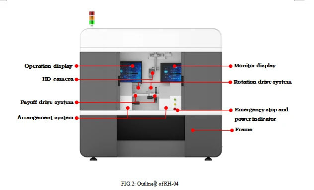
The overall size of the machine is 2200mm (length) × 1100 (width) × 2200mm (height), the movable heavy-duty castors are installed at the bottom with the horizontal adjustment mechanism to facilitate the machine movement and horizontal positioning.
The machine is composed of frame, left and right pay-off drive system, fiber take-up drive system, left and right rotation system, left and right arrangement system, left and right tension control and fiber guide system, and human-computer interface.
The outline of the machine is shown as below:
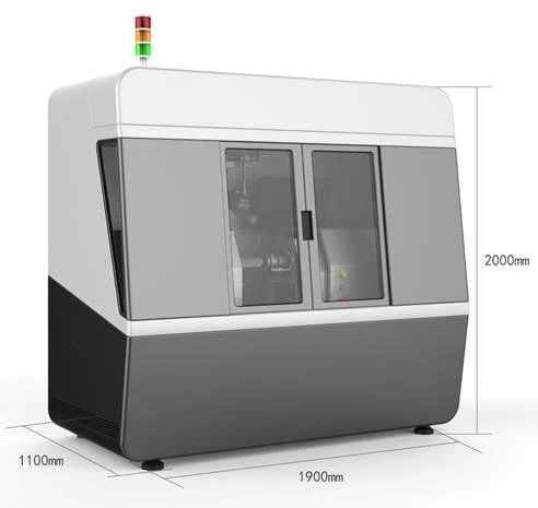
FIG.1: Outline 1 of the RH-04
Pay-off drive system
It is mainly composed of motor, high-precision reducer, and transmission shaft.
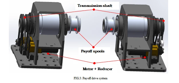
Structure and working principle
This part is used for the payoff process of winding fiber coil, and mainly realize the rotation function of payoff. The motor provides power for rotation, and the rotation is transmitted to the transmission shaft through the high-precision reducer and synchronous belt, and the payoff spools are driven to rotate at a constant speed. The motor speed is adjusted automatically through real-time tension feedback when the user activates the start button on the operation display.
Take-up drive system
It is mainly composed of motor, high-precision reducer and transmission shaft.
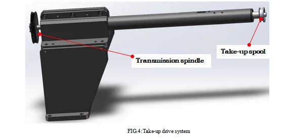
Structure and working principle
This part is used for the take-up process of winding fiber coil, and mainly realize the rotation function of take-up. The user can set the rotation speed, direction on the operation display, and the motor rotation is transmitted to the transmission spindle through the high-precision reducer and synchronous belt, and the take-up spool is driven to rotate at a constant speed. When winding fiber coil, the take-up spool is coaxial mounted on the spindle.
Rotation drive system
Seem as pay-off drive system, it is mainly composed of motor, high precision reducer and transmission shaft.
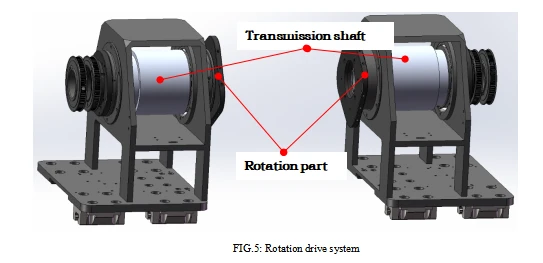
Structure and working principle
This part is used for pay-off rotation process of winding fiber coil, and mainly realize the rotation function of pay-off. The motor provides power for rotation, and the rotation is transmitted to the transmission shaft through the high-precision reducer and synchronous belt, and the payoff spools are driven to rotate at a constant speed. The user can set the rotation speed, direction on the operation display, when working, the inactive pay-off spool keeps relatively static with the take-up spool.
Arrangement system
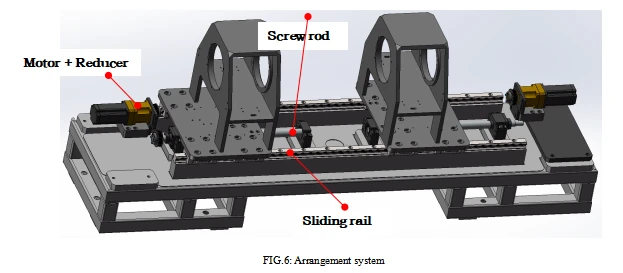
It is mainly composed of high precision sliding rail, screw rod, motor and reducer.
Structure and working principle
This part is used for precise transverse feeding of fiber arrangement. The high reduction ratio reducer is connected with motor, and the reducer drives the sliding table by shaft coupler and high precision screw rod. When winding, according to the take-up speed and fiber diameter, the transverse feeding value is calculated accurately, so that the transvers feeding of sliding table is consistent with the fiber arranging speed, and the precise fiber arrangement can be achieved. The pay-off drive system and tension sensor are placed on the sliding table, and they keep relatively static with the arrangement system during winding.
Tension control and fiber guide system
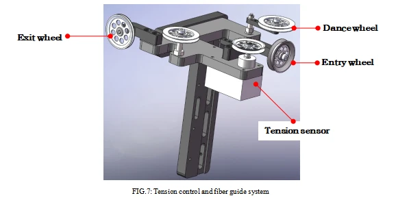
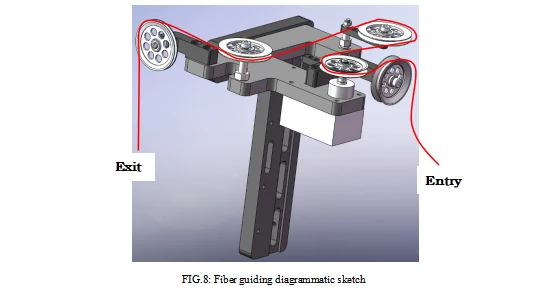
It is mainly composed of tension sensor, fiber guide wheels.
Structure and working principle
Tension sensor and fiber guide system and pay-off drive system are all mounted on the rotation drive system.
The tension sensor has a dance wheel, and the wheel is fixed on a swing arm that can be rotated. There is a tension sensor at the rotation center of the swing arm feeding back the position of the dance wheel to the PLC control system in time, and the system adjusts the pay-off rotation speed according to the dance wheel position.
Electrical Control Scheme
The electrical control system is an important part of the RH-04 winding machine to realize the motion control function and finally achieve the technical performance. Based on the understanding of its technical performance and application requirements, we put forward a technical scheme for the electrical control system of quadrupole winding machine. The main contents include:
--The main components of the electrical control system
--Tension control system
--Precise fiber arrangement system
--Synthesis of control system
--Security protection of system operating
Mature and advanced technologies are adopted in the scheme. The control system adopts the position closed-loop digital compound control architecture which combines the mainstream industrial PC computer and Mitsubishi FX-3U series PLC multi-axis motion axis control system. The friendly graphical man-machine interface provides flexible winding operation and display. The photoelectric incremental shaft-angle encoder with position coding reference signal in high-precision servo motor system is used as the measurement feedback element of each motion axis. PLC axis motion controller and control computer communicate with the upper computer through RS232 to realize remote control. The computer software is based on Windows operating system and has the function expansion ability.
The control computer is the main part of electrical system, and fulfils various control operation, data input and output, the management of various functional module, and equipment fault monitoring and safety protection.
The PLC is the motion control core of all shafts. Through the position closed-loop system composed of drive unit, motion mechanism and shaft-angle measurement feedback unit, Mitsubishi PLC realizes coordinated motion control of each axis, and provides periodic measurement circuit for speed calibration measurement and constant angle synchronous pulse output. The control computer also fulfils various man-machine interface management functions, such as user data input, real-time data output and display of the motion trajectory curve. The high-speed serial interface can realize the communication with the user's remote computer.
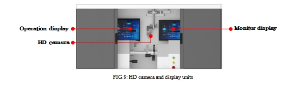
HD Camera and Display Unit
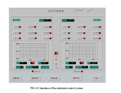
The display unit is divided into two parts: the first part is the camera display unit, the second part is the man-machine interaction interface, which displays the operation functions and parameters of the whole machine.
Industrial Control System
The industrial control system consists of industrial control computer, PLC control system and servo. A man-machine interface control system is installed on the industrial control computer, and forms the whole industrial control system with PLC controller to complete various actions of the machine. The man-machine interface is shown as below:
Operation Steps
Preparation
Turn on the air switch of main power supply (on the side of the machine)
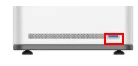 , press the power button on the machine console. At this time, the machine is power on, and the enters the working state.
Check whether there is abnormal alarm in the operation interface
To check whether there are abnormal conditions affecting the normal operation of the machine in each part of the machine.
Check whether there are abnormal conditions affecting the safety in each part of the machine.
Operation
Parameter setting
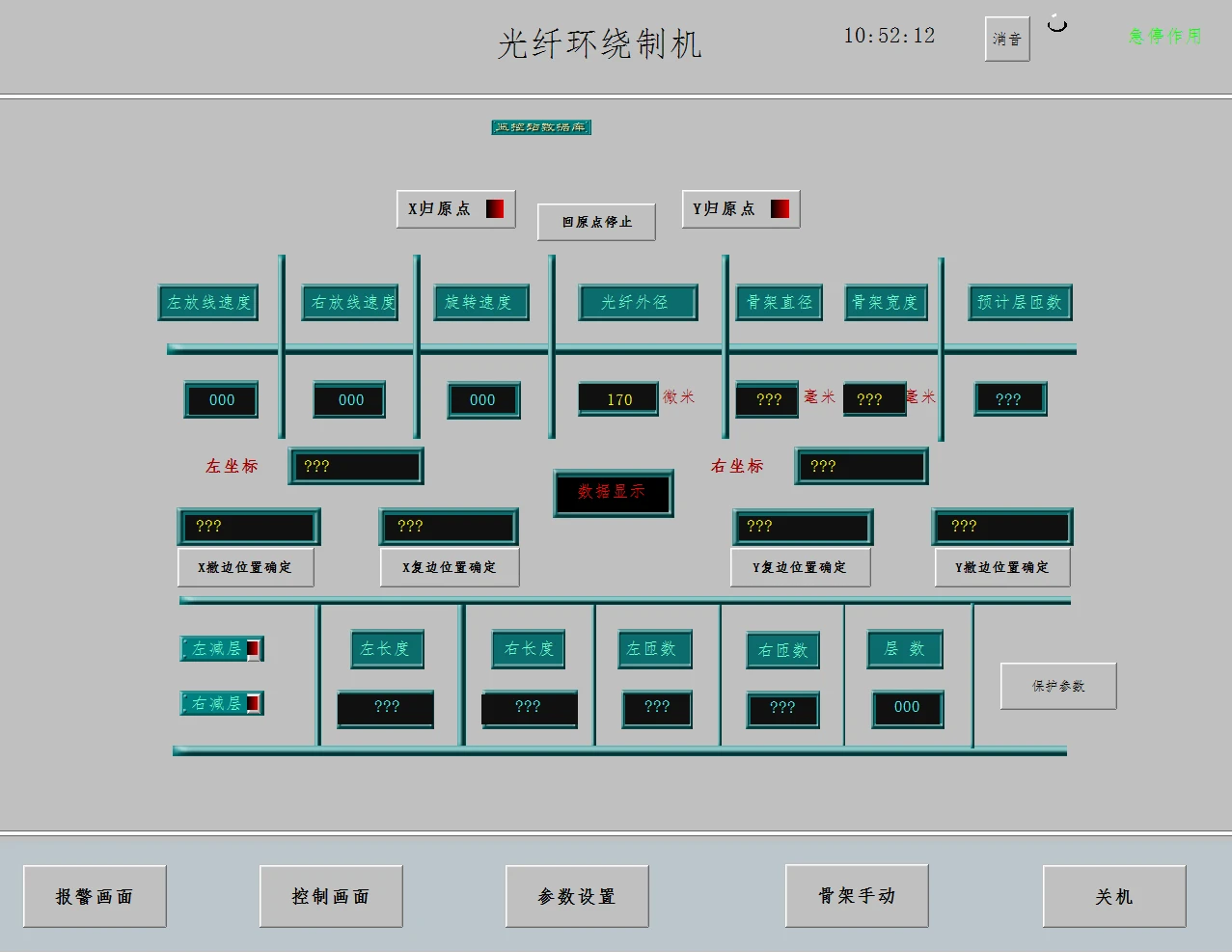
FIG.11: Interface of the parameter setting
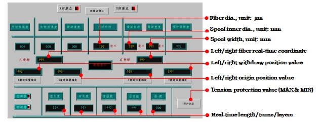
The parameters of winding (such as reel width, reel diameter, and fiber diameter, left/right origin/withdraw position, etc.) are set through this interface. The specific steps are as follows:
Enter the man-machine operation interface - "parameter setting"- to set parameter.
Control steps
The operation of the machine is mainly concentrated on the man-machine interface, and the positions of the operation buttons are shown in the following figure:
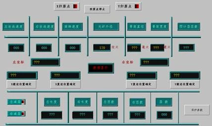
FIG.12: Control interface
Rotation control
 Control the spindle to forward or backward rotate. Green: active, Red: inactive (similarly hereinafter)
Fiber arrangement control

Tension control
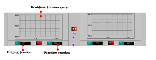
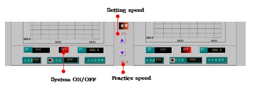
Speed and ON/OFF
Brief Introduction of Winding Fiber Coil
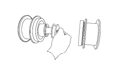
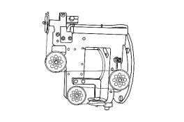
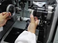
1)Installation of fiber pay-off spool and take-up spool (known as reel of winding fiber)
|
Steps |
Operations |
Diagrams |
|
1 |
Install fiber pay-off spool: Take out a pair of fiber pay-off spool from the spools to be used, and then install them onto the fiber pay-off shaft. Pay attention to lengthen the optical fiber between the two spools to prevent the fiber from being pulled and damaged, and pull the optical fiber according to the correct path without breaking it. |
|
|
2 |
Install the take-up spool: Take out a take-up spool, and its corresponding adapter, shim, and screw, then install them onto the take-up shaft. Attention: before installation, the spool should be cleaned carefully. |
|
|
3 |
Guide the fiber through the guide wheels: Guide the fiber of the two pay-off spools through the guide wheels and take-up spool; then turn the pay-off spools to adjust the tightness of fiber, and make the dance wheel balance. Pay attention not to scratch the fiber to damage coating. Clean up the residual glue in every guide wheel, and then check whether the rotation is normal, whether there is burr caused by collision, to avoid scratching the fiber, and whether the adjustment of the tension dance wheel is normal. |
|
|
4 |
Fasten nuts After the pay-off spools are installed onto shaft, fasten nut and confirm that the spools are fixed by nuts. This step can avoid spool loosening during winding. Attention: don't miss this step. |
|
|
5 |
Adjust the pay-off rack slightly: Rotate the pay-off rack manually to make the incoming angle of fiber meet the operator's sight. |
2)Operation of winding fiber coil(quadrupole)
|
Steps |
Operations |
Diagrams |
|
1 |
Set parameter: In the "control interface", click the "parameter setting" button and input the reel diameter, width and fiber diameter, then return to "control interface" Input setting tension, and rotate the pay-off spools manually to make the practice value to approach setting value. |
|
|
2 |
Adjust left/right pay-off rack: Winding fiber according to quadrupole: use the "X shift forward" and "X shift backward" to move left pay-off rack, and make the fiber of left pay-off spool to align with the right inner side of reel. Meanwhile, use the "Y shift forward" and "Y shift backward" to move right pay-off rack, and make the right rack to move away from the reel, but not to far, and make sure that the left rack would not knock against right rack when rotating. |
|
|
3 |
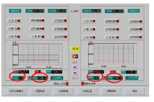
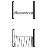
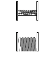
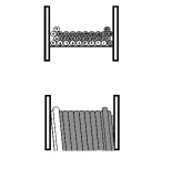
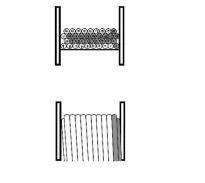
Setting turns and layers: Before winding fiber, click the "left turn number" and "right turn number" once, and the value will be cleared. Then click the "left layer number" to set its value as "1", and click the "right layer number" to set its value as "2". The number of layers here is set according to the total number of layers to ensure the accuracy of length calculation, which is stipulated by the formula for calculating length in the program. |
 |
|
4 |
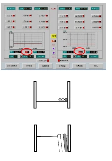
Get ready to wind first layer: The fiber will be wound from the left inner side of the reel, and click " |
 |
|
5 |
Wind the first layer: Click left " |
|
|
6 |
Bridge from layer 1 to layer 2 When the fiber of left pay-off spool approaches the left inner side of the reel, you should decrease the speed, and arrange the fiber manually. When the fiber reaches the left inner side of the reel, you should set the speed as "1", and wind a turn of fiber of left pay-off spool onto the groove between the first turn and the second turn on the left of the first layer, and then click left "ON" to "OFF" to stop the machine. |
|
|
7 |
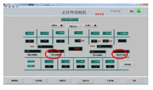
Set left origin and left withdraw: At this time, the position of the left rack is the origin position of the normal winding, and it is also the position to be rewound next time. In the "configuration screen" interface, click "X origin location confirm" and "Y withdraw location confirm", the corresponding coordinates will be set automatically. |
|
|
8 |
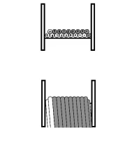
Wind the second layer: Click "X shift backward", make the left rack to move away from the reel; then click "Y shift forward", make the fiber of right pay-off spool to align with the first fiber of layer 1 on the right reel. Begin to wind the second layer (fiber from right pay-off spool): Click left/right "OFF" to "ON", right "wind", "Y auto follow forward",and set the speed as "1", according to the winding condition, you can increase the speed. The fiber of right pay-off spool should wind onto the groove between turns of the first layer, and wind from right to left. |
|
|
9 |
Wind the last turns of layer 2: When the right rack approaches the left inner side of the reel, you should decrease the speed, and arrange the fiber manually. Meanwhile, pay attention to the position of left and right rack, and make sure that the right rack would not knock against left rack when rotating, if necessary, you should stop to click "X shift backward" to adjust the position. When the left fiber and right fiber cling together, finish the last turn of the right fiber on the layer 2, and click right "ON" to "OFF" to stop the machine. Click "right turn number" to increase the number of layers by 1, and the right layer number will change from 2 to 3, meanwhile, click "left turn number" three times to make the left layer number to change from 1 to 4. |
|
|
10 |
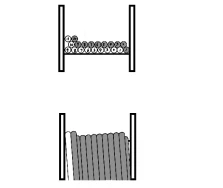
Bridge from layer 2 to layer 3, and wind the third layer: Return the right rack to its original position, and move the right rack back forward, make sure that the right rack would not knock against left rack when rotating. Click left/right "OFF" to "ON", and click left "wind", and wind a turn of fiber of left pay-off spool onto the groove between the first turn and the second turn on the left of the second layer, and then click left "ON" to "OFF" to stop the machine. Click "X shift backward" and "Y shift forward", and make sure that the left rack would not knock against right rack when rotating. Click left/right "OFF" to "ON", right "wind", "Y auto follow backward", and increase speed gradually. During winding, you can use auxiliary tool to arrange fibers. |
|
|
11 |
Bridge from layer 3 to layer 4, Set left withdraw and right origin: When the right rack approaches the right inner side of the reel, you should decrease the speed, and arrange the fiber manually. And when the fiber clings to the inner side, the speed should be set as 1, wind a turn of fiber of the right pay-off spool onto the groove between turns of the third layer. Then click right "ON" to "OFF" to stop the machine. At this time, the position of the right rack is the origin position of the normal winding, and it is also the position to be rewound next time. In the "configuration screen" interface, click "Y origin location confirm" and "X withdraw location confirm", the corresponding coordinates will be set automatically. Now, the original coordinates and withdrawing coordinates of left/right rack have been set completely. The original coordinates are the origin of winding fiber, and the withdrawing coordinates is the coordinates that the left/right rack would not knock against each other. Attention: the withdrawing position should be suitable and avoid hurting the fiber. |
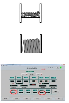 |
|
12 |
Wind the firth layer Click "X origin" and "Y withdraw", and make the fiber of left pay-off spool to align with the left inner side of the reel and make the right rack to move away from the reel. Click left/right "OFF" to "ON", click left "wind" and "X auto follow forward", and set speed as 1, and then increase speed gradually. |
|
|
13 |
The last turn of layer 4 When the fiber of left pay-off spool approaches the right inner side of the reel, you should decrease the speed, and arrange the fiber manually. After finish the last turn of left pay-off spool, click right "ON" to "OFF" to stop the machine. Click "left turn number" to increase the number of layers by 1, and the left layer number will change from 4 to 5, meanwhile, click "right turn number" three times to make the right layer number to change from 3 to 6. |
|
|
14 |
The second quadrupole,winding layer 5-8: When finish layer 4, repeat the above steps. |
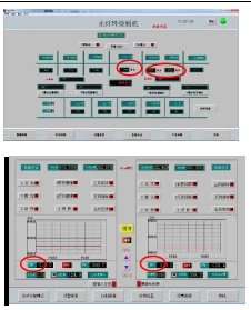
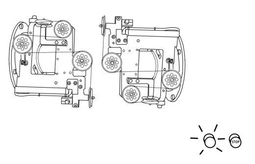
 " on both sides to "ON", and click "
 wind", and set speed as "1", the first turns of fiber should be aligned with inner side of reel, and increase speed gradually.
 wind" and "
 X auto follow backward", then click "speed", increase speed gradually, and the fiber of left pay-off spool should cling against the first turn fiber. Start to wind fiber of left pay-off spool, and click "
 left turn number", the turn number will be cleared and the counter begins to count. During winding, the use of auxiliary tool should be avoided to reduce the influence of additional stress on fiber. After adjusting auto-following, let fiber wind naturally and try not to interfere it.

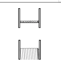
Alarm and clear
Alarm status
When a warning message appears during the automatic or manual operation of the machine, it means that the machine is in the fault alarm state and the machine is in the suspended state. At the same time, the interface usually displays the fault information.
Clear the alarm
According to the fault information displayed on the operation interface or through observation to identify the fault, after the fault is eliminated, the alarm will be released and the machine will return to the original operation state.
Emergency stop
In case of emergency, please press the red "emergency stop" button immediately.
At this time, the machine is shut down immediately and all operations are disabled, and there is no warning in operation monitoring. After troubleshooting, rotate the "emergency stop" button to make it pop up and reset. Press the reset button to remove the fault.

Operation Precautions
When the machine is running, please keep the operator away from the equipment body to avoid personal injury.
For fiber with diameter less than 170μm(including 170μm), please do not operate the machine at high speed (300m/min or more). Because small diameter fibers are easy to damage at high speed, it is suggested that the speed should be controlled within 200m/min.
Please do not turn off the power supply when the machine is in normal running, so as to avoid serious injury to the machine.
Please check the easily worn and vulnerable parts of the machine regularly
Please maintain all moving parts timely, such as shaft of fiber arrangement part, shaft of guide wheel, etc.
Please draw the warning line in the place where the machine is used, so as to avoid personal injury caused by fiber crack during high-speed winding.
Periodic Maintenance Table
|
Type |
Checking period |
Checking contents |
|
Daily checking and maintenance |
Daily |
Check the temperature, humidity, dust, foreign matters, etc. |
|
Check for abnormal vibration and noise. |
||
|
Check whether the power supply voltage is normal. |
||
|
Check for odor |
||
|
Check the cleanliness of the front of the servo driver and the connector |
||
|
Check whether the wire has been damaged |
||
|
Check the connection part of the machine for looseness and deviation |
||
|
Check whether there are foreign matters in the load area |
||
|
Check whether the guide wheel is clean, smooth and stable |
||
|
Check whether the tension control system is flexible and free from jamming |
||
|
Please use clean and dry dust-free gauze to wipe the surface of the machine, slide table and fixed parts for reel. The small parts such as the fiber guide wheels need to be cleaned with tweezers and cotton. |
||
|
Periodic check and maintenance |
weekly |
The guide-rail, sleeve and cone of the reel fixing parts are wiped and lubricated by the personnel with sewing oil |
|
monthly |
Pay-off shaft connection screw is fastened |
|
|
Take-up shaft connection screw is fastened |
||
|
The fixing screws of the arrangement guide-rail is fastened |
||
|
Check that the shaft of the guide wheel is in the same plane |
||
|
Lubricate every working shaft |
||
|
Annual |
Check whether the wire of driver is loose |
|
|
Check whether the connection plug of servo motor and driver is loose |
||
|
Check whether the grounding wire of each device is reliable |
||
|
Check the rotating shaft |
Common Faults & Treatment Method
|
No. |
Faults |
Causes |
Treatment methods |
Notes |
|
1 |
The main power plug of the machine is plugged, but the machine has no power |
There is no electricity of the power socket The air switch Q1 in the electric cabinet is not closed The power button on the operation panel is not pressed |
Connect the main power socket to the power supply Turn on the air switch Q1 in the electric cabinet Press the power button on the operation panel |
Danger! Electricity! Danger! Live wire! |
|
2 |
The machine is powered on, but the display panel of servo drivers such as fiber arrangement, pay-off, take up has no signal. |
The air switches Q1 - Q7 of the servo drivers for fiber arrangement, pay-off and take-up are not closed |
Turn on the air switches Q1-Q7 in the electrical cabinet |
Danger! Electricity! Danger! Live wire! |
|
3 |
PLC module does not work |
1There is no power supply for PLC module 2PLC mode is "STOP" |
1Turn on air switch Q9 2Switch PLC mode to "RUN" |
Danger! Electricity! Danger! Live wire! |
|
4 |
The left and right "OFF/ON" button do not light up |
The tension is too large or too small, or the upper / lower limit value of tension protection is set too small |
Adjust the tension manually to make the tension within the upper / lower limit of the tension protection value or set the protection value higher |
Danger! Electricity! Danger! Live wire! |
|
5 |
The alarm box indicates "left limit or right limit" alarm, and the indicator light is on |
When the slider reaches the limit position, the machine is protected. |
When the left/right limit alarm of guide rail happened, please press the emergency stop button and turn the guide screw rod to reset manually. Keep the base of fiber arrangement part away from the left/right limit protection switch |
The power must be turned off |
Hot Tags: rh04 fiber coil winding machine, China rh04 fiber coil winding machine manufacturers, factory