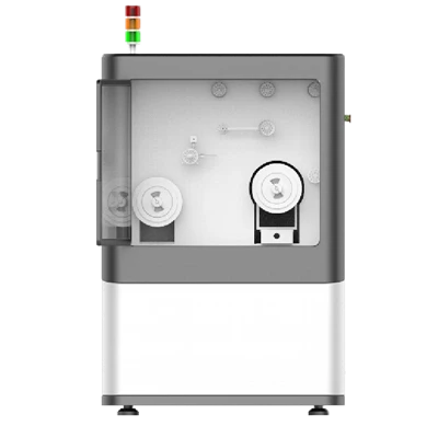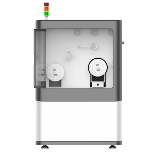
FX03 Fiber Separating And Rewinding Machine
Tension Accuracy: ±1g
Tension Over-Limit Protection
Human-Machine Interface (HMI)
Description
Key Features
- Rewinds 25 km standard fiber spools
- Length Error: 0.3%
- Tension Range: 8g-50g
- Tension Accuracy: ±1g
- Tension Over-Limit Protection
- Human-Machine Interface (HMI)
Applications
- Fiber Rewinding or Separating
- Fiber Coil
- Delay Coil
Product Introduction
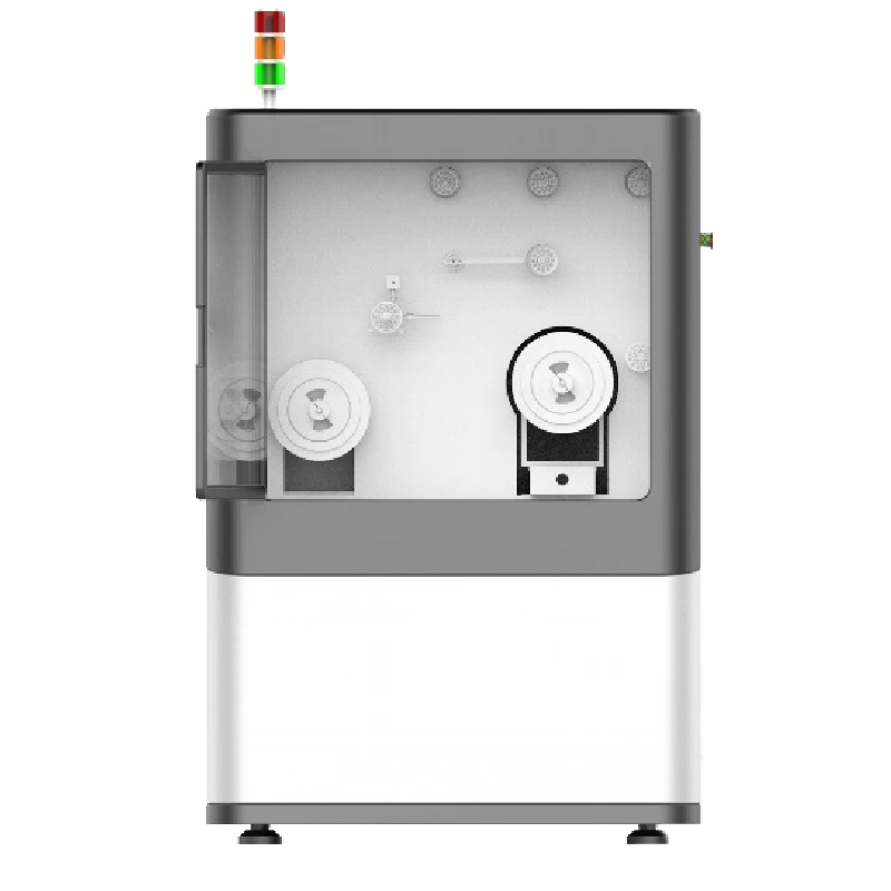
Company's FX03 fiber rewinding machine is dedicated to fixed-length winding and fiber re-spooling. Entering the target length via the HMI lets it complete fixed-length winding and auto-stop unattended, enabling production automation and higher efficiency. The machine comprises an active pay-off system, a tension control system, and a precision traverse system. A servo motor drives a ball screw to move the take-up spool axially for even layering. The tension system acquires real-time tension, compares it with the setpoint, and via PID control adjusts the pay-off motor speed to keep the dancer wheel balanced-ensuring stable tension throughout.
Unique Technology
Company is a high-tech enterprise with full closed-loop capabilities from fiber winding equipment and coils to FOGs, fiber/MEMS inertial products, IMU circuits, software, and test equipment. End-to-end process control improves quality and reduces costs. Operating under ISO9001 with strict processes, it ensures product reliability and consistency.
Parameters
FX03 Fiber Separating and Rewinding Machine Specifications
|
Parameter |
Specifications |
|
Applicable Fiber Diameter Range (mm) |
φ0.1~0.26 |
|
Max. Operating Speed (R/min) |
500 |
|
Tension Control Range (g, speed < 200 R/min) |
8-15 |
|
Spindle Diameter (mm) |
15 |
|
Max. Fiber Spool Diameter (mm) |
300 |
|
Length Calculation Error (‰) |
3 |
|
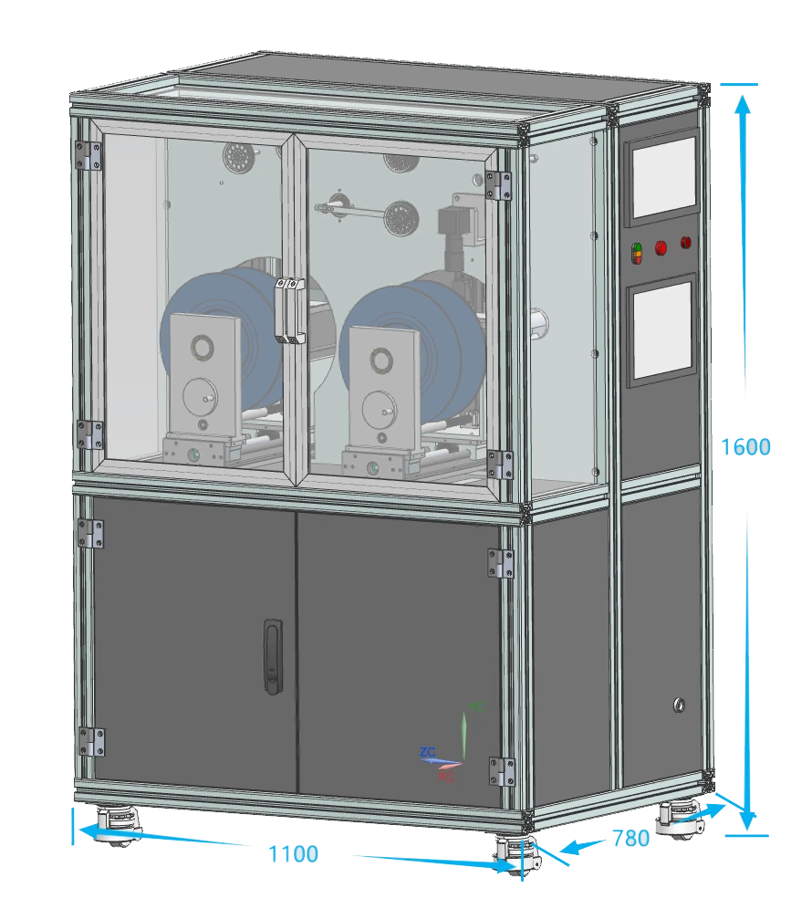
Equipment Dimensions (mm) |
L 1100 × W 780 × H 1600 |
|
Equipment Voltage (V) |
220 |
|
Equipment Power (kW) |
2.0 |
Outline Drawing
Safety Precautions
To ensure safety and avoid injury or damage, be sure to observe the following safety precautions.
This manual contains important information about the operation, maintenance and safety precautions of the Fiber Optic Rewinding Machine, so please read the contents carefully before use.
WARNING Indicates a potentially hazardous situation that, if not avoided, could result in death or serious injury.
WARNING
- Only qualified personnel familiar with this equipment and the attached files are permitted to operate or overhaul the equipment.
- Do not plug and unplug the power supply or touch the air switch with wet hands to avoid electric shock.
- Do not use if the power line or plug is damaged, to avoid fire due to heat.
- Do not touch any rotating part of the equipment when the equipment starts to run, to avoid personal injury.
- Do not touch cabinet terminals, switching power supply and other electrically charged components inside the electric box to avoid electric shock.
The user is responsible for any damage to the equipment or personal injury caused by the user's inability to operate the equipment in accordance with the operating instructions and precautions.
Safety Instructions
Before operation, read the following section carefully for personal safety!!!!
WARNING!
- Dangerous voltages and rotary movements are present in some parts of this equipment during operation.
- Failure to observe safe operation may cause serious personal injury or property damage.
- Only qualified personnel who first thoroughly understand the following warnings, precautions and maintenance procedures should operate this equipment or work around it.
- The key to safely using this equipment to produce acceptable products is proper operation and maintenance procedures.
Qualified Personnel:
- Refers to people familiar with the operation and maintenance of this equipment and must have the following qualifications:
- Personnel trained and qualified in power supply, disconnection, cleaning, earthing, marking of wiring and electrical equipment in accordance with safety regulations.
- Personnel trained in the proper maintenance and use of protective equipment in accordance with safety regulations.
- Personnel trained in emergency care.
DANGER!
Refers to possible death, serious injury or damage if not taking proper precautions.
ATTENTION!
Refers to relevant parts of product information and manuals that should be given high priority.
Equipment Maintenance
Only qualified personnel familiar with this equipment and the attached files are permitted to operate or overhaul the equipment.
All panels and doors of the equipment must be closed during normal operation, and it is prohibited to touch production parts with hands to avoid personal injury.
Be sure to disconnect the AC power before performing visual inspection and maintenance work. Both the controller and the motor may carry dangerous voltages before disconnecting the AC power supply, even after the controller contactor is disconnected, which need to be released from the charge before operation (the best way is to leave it for a while after disconnection, waiting for the charge to be released).
Under no circumstances should you touch the energized wiring during energized measurements.
Ensure good grounding conditions and safe operation of the equipment. Due to the many uses of controllers and other components, this equipment may carry high induced voltages, which must be safely grounded.
When working on energized parts, it is important to stand on an insulating surface, to avoid direct contact with the earth.
Untrained personnel should not touch the original electrical appliances, terminals, etc., after the equipment is energized so as not to cause personal injury; If you find the wires fall out, please disconnect the power before reconnect it.
Follow the instructions carefully and observe the precautions concerning "DANGER" and "WARNING".
Turn off the power when cleaning the equipment. Do not wipe with the equipment is connected to electricity. Do not flush with water.
Please strictly follow the equipment operation steps to ensure the production of qualified products; for other notes on maintenance, please contact us.
Installation Instruction
The flooring where the equipment is installed is required to be level.
Only who are familiar with the electrical schematic connection diagram of the equipment may carry out the electrical connection of the equipment.
The internal wiring has been completed before leaving the factory. Before normal operation, please check the wiring carefully, preventing the joints from loosening during transportation due to the bumps of transportation, causing the equipment's malfunction.
Environment Requirements
To produce qualified products and extend the service life of the various components, the operating environment needs to possess:
Power supply
Single-phase three-wire 220V (±10%), 50Hz, 2.0KW
Users need to provide good grounding conditions for the equipment (independent grounding devices designed in accordance with international standards, personnel protection and a certain degree of elimination of electromagnetic interference.
Installation Environment
Temperature: 0-30°C, NO dust.
Relative humidity in the range of 20-90% (no condensation).
No corrosive or flammable gases.
Well-ventilated conditions to facilitate heat dissipation from the equipment.
Product Introduction
Fiber Optic Rewinding Machine is specially designed for fixed-length winding and rewinding of optical fibers. By inputting the target winding length through the interface, it can complete the fixed-length winding and automatically stop without human involvement, so as to realize the production automation and improve the production efficiency.
Product Features
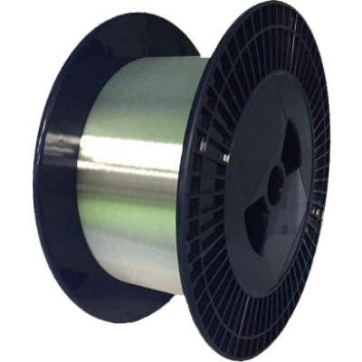
Perform rewinding tasks for 25KM standard fiber transport trays and customer specific spools.
Adopt servo driver to control the arrangement of fiber with high accuracy.
Adopt active fiber pay-off structure in the pay-off part of the take-up spool, which ensures the stability of fiber tension during the whole fiber rewinding process. Tension control accuracy is during ± 2g. (The seller will provide tension calibration once before the equipment leaves the factory, generally set to 15 ± 2g).
High-precision meter gauge to ensure the accuracy of meter length, avoiding the waste of fiber.
The whole machine adopts PLC control, each unit parameter is displayed on the touch screen and relevant operation information can be recorded.
With left and right limit stopping protection, to prevent damage to the mechanical parts caused by wrong operation.
Equipped with a buzzer, alarm info in the touch screen can remind the user of the abnormality.
Main Parameters
|
No. |
Parameter |
Specifications |
|
1 |
Fiber Diameter Range |
φ0.1~0.26mm |
|
2 |
Maximum Operating Speed |
500RPM |
|
3 |
Tension Control Range |
8g-50g (speed < 200 RPM) |
|
4 |
Main Shaft Diameter |
15mm |
|
5 |
Max Pay-off Spool Diameter |
300mm |
|
6 |
Length Calculation Error |
3‰ |
|
7 |
Dimension |
L*W*H:1100×780×1600 mm |
|
8 |
Voltage |
220v |
|
9 |
Power |
2.0KW |
For details of the parameters, please refer to the technical annex of the sales contract. Parameters mentioned in this manual are within the scope of the sales contract.
Equipment Composition and Principle
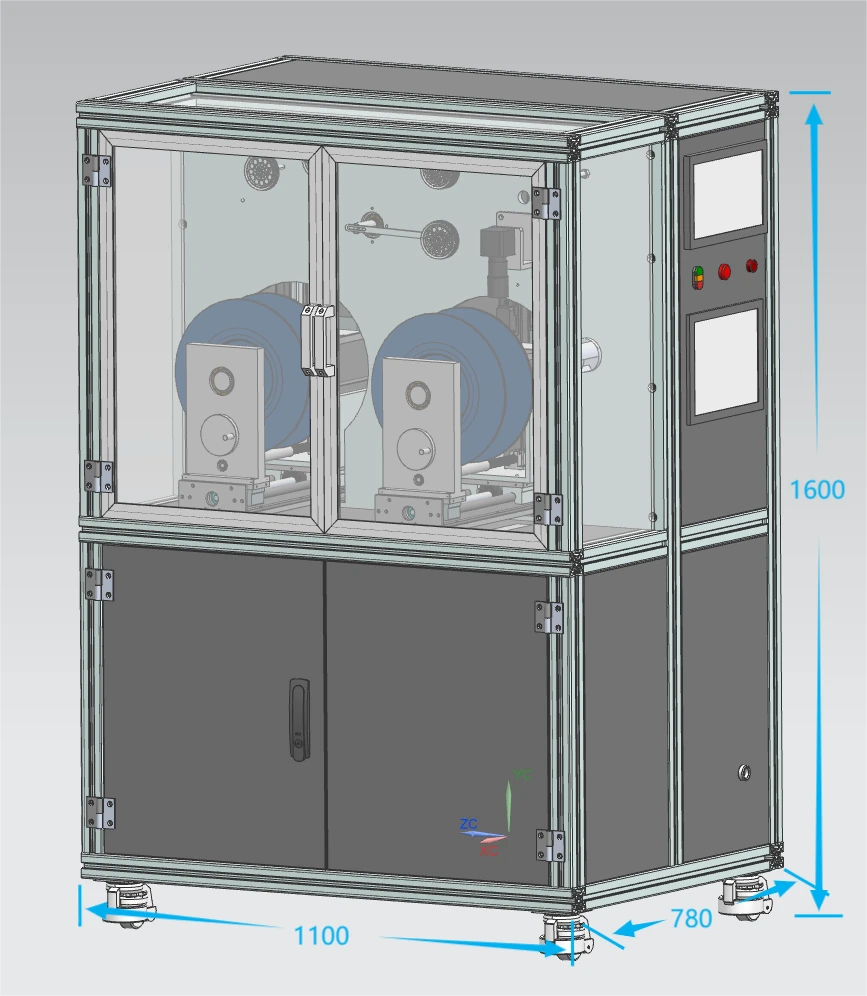
Equipment Composition
Pay-off and take-up systems
Chucking device
Fiber arranging rail systems
Touch panel
Fiber guide wheels
Tension control system
Meter counters
Note: For specific structure, please refer to the technical annex of the sales contract. Parameters mentioned in this manual are within the scope of the sales contract.
Structure and Principle
The machine is divided into several parts: active fiber pay-off system, tension control system, precision fiber arranging system and so on.
The power is provided by AC servo motor (400W).
The fiber arranging system is driven by servo motor to rotate the screw rod, which makes the take-up spool move along the direction of the axis to realize the fiber arranging.
Tension control system, collect the present tension, by comparing the PV with SV, adjusted by PID, and fed back to the pay-off motor, which adjusts the output speed according to the received control signal, making the dance wheel in a relatively balanced position, thus achieving tension stabilization.
The speed of the pay-off motor can be adjusted with the control signal from the tension sensor so that the tension of the fiber is kept at a relatively stable value.
Equipment Operation
Procedure
Press the power button, the machine is powered on, select the "chinese" or "English" interface, then view the main interface on the control screen, and turn on the "Servo" switch.
Click the Setup button to enter the setup interface, and then click the three buttons of "Clear Tension", "Reset Pay-off Spool" and "Reset Take-up Spool".
After the take-up and pay-off spool rail return to the mechanical origin, adjust other parameters on the parameter interface, including " Length", " Speed", "Take-up and Pay-off Spool Width", "Take-up and Pay-off Spool Flange Thickness", "Take-up and Pay-off Fiber Pitch", "Take-up and Pay-off Rail Original Position" and so on.
Back to the main interface, click on the two "Reset" button, wait for the two rails to return to original position.
Turn off the "Servo" switch, fix the take-up and pay-off spools on the machine, and adjust the fiber path so that the oscillating wheel is fixed in the level position.
Turn on the "Servo" switch and press the two "Reset" buttons again to prevent position deviation when the servo is turned off.
Re-confirm the fiber is at the same level with the wheel, which can be adjusted by " ", "
 ", and determine whether "Forward " or "Backward ".
After checking, click on the "Length Clear" button, and then click on the "Start" button. The machine starts running. (protective door need to be closed).
Waiting for the machine to rewind the fiber, if the fiber and the wheel are not in the same plane, click on the "Forward", "Backward" to adjust the position of the take-up and pay-off rails.
When the present length reaches the set length, the machine stops automatically and completes the rewinding mission.
Touch panel interface description and operation method:
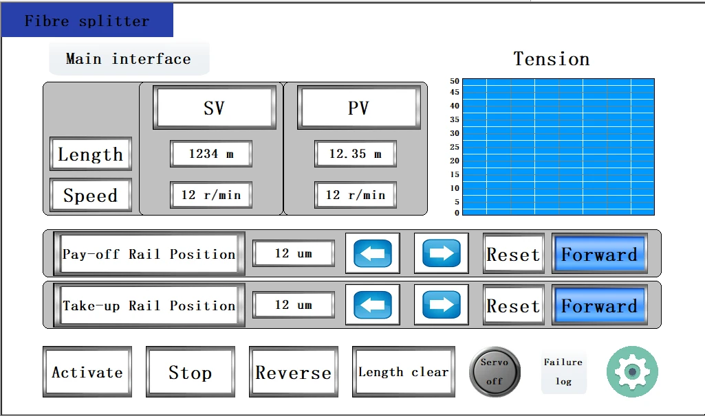
Main Interface:
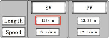 Display the length of the fiber required for the setting. (in M)
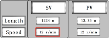 Display the speed of take-up spool spindle. (in r/min)
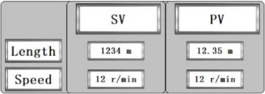 Display the present fiber length that has been wound. (in M)
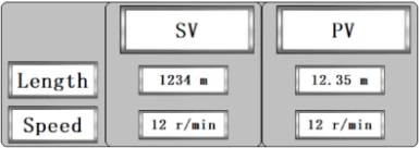 Display the present winding speed. (in r/min)
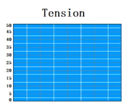 Display the present tension on the fiber. (in g)
 Display the present position of pay-off rail, not adjustable.
 Display the present position of take-up rail, not adjustable.

Non-start Status: controls the forward movement of the take-up and pay-off rails;
Start status: controls the acceleration or deceleration by 3 times of the take-up and pay-off rail movement.

- Non-startup status: controls the backward movement of the take-up and payoff rails;
- Start status: controls the acceleration or deceleration by 3 times of the take-up and pay-off rail movement.
 Move the take-up and pay-off rails to the position before startup according to the position setting in the setting interface.
 /
 Control the forward or backward movement of the take-up and pay-off rails before the device is started.
 To turn on the equipment.
Slowly stops the equipment, the speed will gradually reduce;
When the equipment alarms, this button can stop the buzzer alarm;
Do not use this button when the equipment is in high-speed operation. If requiring an immediate stop, press the red "Emergency Stop" button on the body of the machine.
 /
 Switch between forward and backward fiber arrangement, pay attention to the current status of this button before pressing.
 Clear the actual rewind length recorded by the device, for the precise display of next time.
 /
 :Servo switch of the motor; when closed, take-up and pay-off spools can be toggled to adjust the position; when opened, take-up and pay-off spools cannot be toggled, and can only be controlled by setting in the interface. This switch needs to be on when you press the buttons related to the movement of the motor.
 To access the Failure Log screen.
 To enter the parameter setting interface.
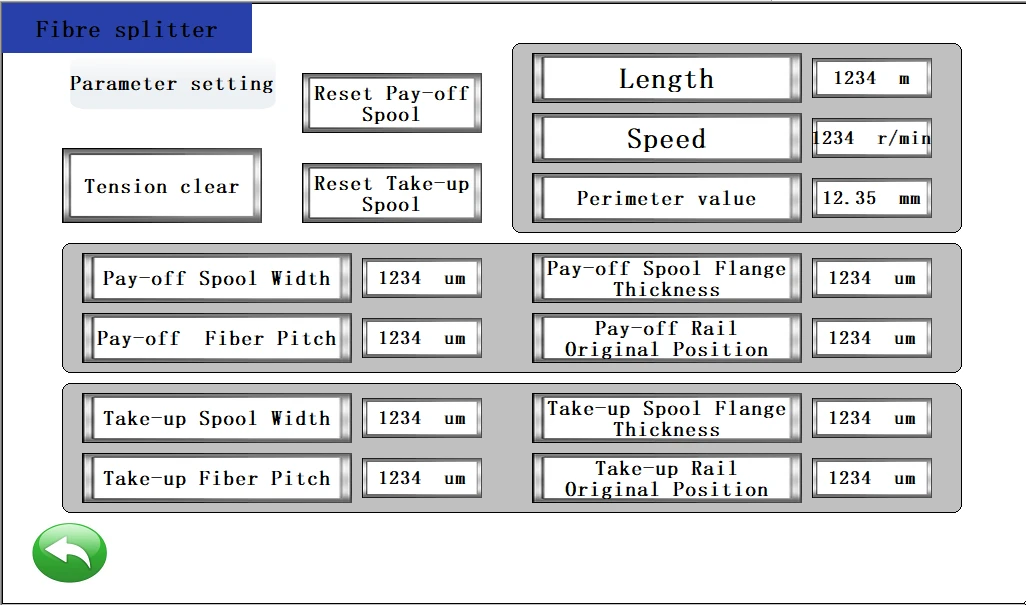
Parameter setting interface description
 To clear the excess tension, click on this button once the machine is on.
 Determines the position of the mechanical origin of the pay-off rail, click on this button once the machine is on. (clicked with the servo on)
 Determines the position of the mechanical origin of the take-up rail, click on this button once the machine is on. (clicked with the servo on)
 Set the fiber length that need to be rewound, in m. Click the input box, insert number and press "ENT" or "confirm".
 Set the rewinding speed according to needs, in r/min. Click the input box, insert number and press "ENT" or "confirm".
 Input the perimeter value of the meter gauge wheel, perimeter of the meter gauge in this device is 200mm, which can be fine-tuned to achieve the most accurate.
 Enter the width of the pay-off spool, in um.
 Enter the flange thickness of the pay-off spool near the side of the panel, in um.
 Enter the pitch value of the fiber arrangement, in um, which is generally the same as or larger than the outer diameter of the fiber, e.g., 260um.
 Enter the original position of the pay-off rail, in um.
 Enter the width of the take-up spool in um.
 Enter the flange thickness of the take-up spool near the side of the panel, in um.
 Enter the pitch value of the fiber arrangement, in um, which is generally the same as or larger than the outer diameter of the winding fiber, e.g., 260um.
 Enter the original position of the take-up rail, in um.
In the setting interface, the relationship between width D, flange thickness H, origin S of the take-up and pay-off rails, and the round trip of pay-off and take-up spools are as follows:
When the machine starts up, the actual position will go back and forth between (S-H-D) ~(S-H), (S-H-D) is the minimum position value, and (S-H) is the maximum coordinate value. When clicking Reset in the main interface, the position of the take-up and pay-off rails will move to the minimum position (S-H-D), and the default fiber arrangement direction is forward.
The origin S has generally been adjusted to a standard position, so it does not need to be changed frequently. If user need to adjust, set the width D and flange thickness H to 0, adjust the value of origin S, click on the Reset in the main interface, the present position will be the origin S, and then observe whether the rubber surface and the corresponding wheel are in the same level.
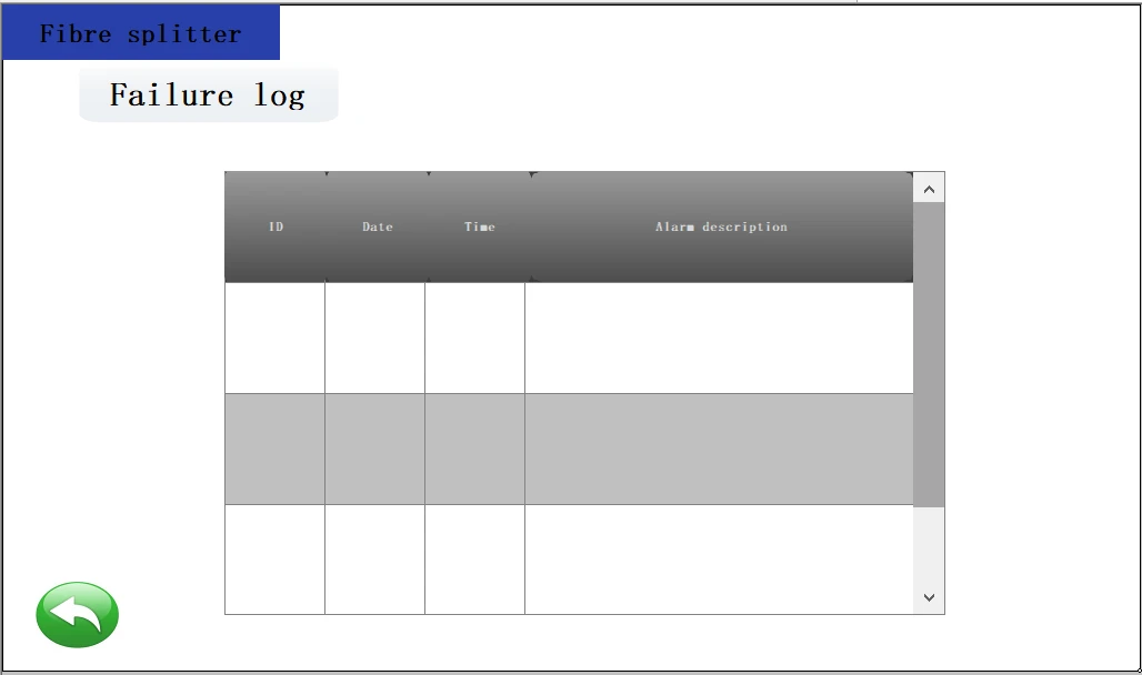
Failure Log Interface
To view the detailed alarm causes of recent devices, including date, time, and alarm description, for example:

 ,
 , etc.
Handling Precautions
Please keep away from the equipment when the equipment is running to avoid injury;
Do not use fiber with diameter smaller than 170um (including 170um) at high speed (300m/min and above). Small diameter fibers are easily damaged at high speeds. It is recommended to control the speed within 200m/min.
Do not turn off the power while the equipment is in normal operation as this may cause significant damage;
Please check each wearable and fragile part of the equipment regularly;
Please perform timely maintenance on all moving parts, such as rail bearings, guide wheel small bearings and other parts;
Please draw a warning line where the equipment is to be used to avoid injury caused by fiber breakage during high-speed operation;
Periodic Maintenance Schedule
|
Item |
Frequency |
Inspection Content |
|
Normal Check |
Daily |
Operating temperature, humidity, dust, etc. |
|
Abnormal vibration and noise |
||
|
Power supply voltage |
||
|
Abnormal smell |
||
|
Cleanliness of the front of the servo drive, connectors |
||
|
Wiring |
||
|
Connection parts with equipment and deviation of core feet |
||
|
No objects embedded in the load section |
||
|
Cleanliness, smoothness and stability of guide wheel |
||
|
The tension control system movement is flexible, no stuttering |
||
|
Period Check |
Monthly |
Tightening of pay-off bearing attachment screws |
|
Tightening of take-up bearing attachment screws |
||
|
Tightening of fiber arrangement fixing screws |
||
|
Guide wheel bearing positioning is in the same plane |
||
|
Lubrication of each working bearing |
||
|
Yearly |
Wiring of the drive is tight |
|
|
Connection plugs between servo motor and drive is tight |
||
|
Grounding wire of each device is secure |
||
|
Rotating bearing inspection |
Common Failures and Handling Methods
|
No. |
Failure |
Cause |
Handling |
Notes |
|
1 |
No power after connection to electricity |
No power in the mains plug socket; Air switch q1 in the electrical cabinet is not closed; |
Mains plug socket connect to electricity Close the q1 air switch in the electrical cabinet. |
Be careful of electrocution. |
|
2 |
The equipment is powered, no display of pay-off, take-up and fiber arrangement servo drive in the panel |
Air switch Q2, Q3, Q4, Q5, Q6 of fiber arrangement, pay-off and take-up servo drive is not closed |
Close air switches Q2, Q3, Q4, Q5 and Q6 in the electrical cabinet. |
Be careful of electrocution. |
|
3 |
PLC module not working |
PLC module not energized PLC mode is "STOP". |
Close the air switch Q7 Switch the PLC mode to "RUN". |
Be careful of electrocution. |
|
4 |
The alarm box indicates "Pendulum angle exceeds the lower limit, or the upper limit ". |
Tension balancer not in horizontal position |
Manually adjust the tension bar to keep horizontal |
Be careful of electrocution. |
|
5 |
Machine not working after pressing the "Start" button does not operate the device. |
Parameters not entered The alarm box indicates "pendulum angle exceeds the lower limit, or the upper limit ". Servo switch not turned on |
Correctly enter fiber spacing and perimeter value Manually adjust the tension bar to keep horizontal Turn on the servo switch |
Attention |
|
6 |
After pressing the "reset" button, the equipment runs for a few seconds and then stops. |
Take-up and pay-off servo drive breakdown |
Refer to the servo drive manual to find the cause of the corresponding alarm number. |
Inspection after power cut |
|
7 |
Press the "Start" button and the unit runs for a few seconds and then stops. |
Take-up and pay-off servo drive breakdown |
Refer to the servo drive manual to find the cause of the corresponding alarm number. |
Inspection after power cut |
Hot Tags: fx03 fiber separating and rewinding machine, China fx03 fiber separating and rewinding machine manufacturers, factory