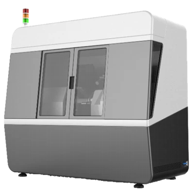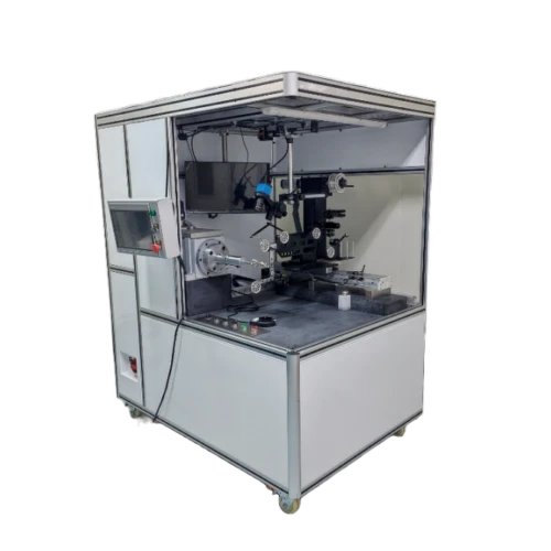
RH16A Fiber Coil Winding Machine
Meets the winding requirements for quadrupole, octupole, and hexadecapole fiber coils
Fully sealed welded structure with strong shock absorption
Precise automatic fiber placement
Real-time display of winding length, number of turns, number of layers, etc.
Description
Key Features
- - Meets the winding requirements for quadrupole, octupole, and hexadecapole fiber coils
- - Fully sealed welded structure with strong shock absorption
- - Precise automatic fiber placement
- - Real-time display of winding length, number of turns, number of layers, etc.
Applications
- Winding fiber coils
Product Introduction
Company's RH16AA multi-pole fiber coil winding machine is the core FOG fiber-coil equipment with proprietary R&D and manufacturing technology. It winds coils via symmetric or flat-winding processes with precise automatic layering and glue dispensing. Its base mounts heavy-duty casters and a leveling mechanism for mobility and positioning. During winding, the layering feed is computed from take-up speed and fiber diameter so the precision slide stays matched for balanced, precise layering; the pay-off drive and tension sensor are co-mounted and remain relatively stationary.
Unique Technology
Company is a high-tech enterprise with full closed-loop capabilities from fiber winding equipment and coils to FOGs, fiber/MEMS inertial products, IMU circuits, software, and test equipment. End-to-end process control improves quality and reduces costs. Operating under ISO9001 with strict processes, it ensures product reliability and consistency.
Parameters
RH16A Fiber Coil Winding Machine Specifications
|
Parameter |
Specifications |
|
Fiber Diameter Range (mm) |
Φ0.1~Φ0.5 |
|
Winding Speed (r/min) |
0-80 |
|
Maximum Tooling Diameter (mm) |
250 |
|
Tension Control Range (g) |
3-50 |
|
Tension Precision (g) |
±0.5(20r/min) |
|
Traverse Stroke (Coil Width) (mm) |
200 |
|
Counting Accuracy (turns) |
0.01 |
|
Displayable Parameters |
Turns, Tension, Length, Layer Count, Spindle Direction, Traverse Direction, Coordinate, Speed, real-time display of wound length for current layer |
|
Programmable Parameters |
Fiber Diameter, Spindle Direction, Traverse Direction, Speed, Tension, Spool Diameter, Spool Width, etc. |
|
Equipment Dimensions (mm) |
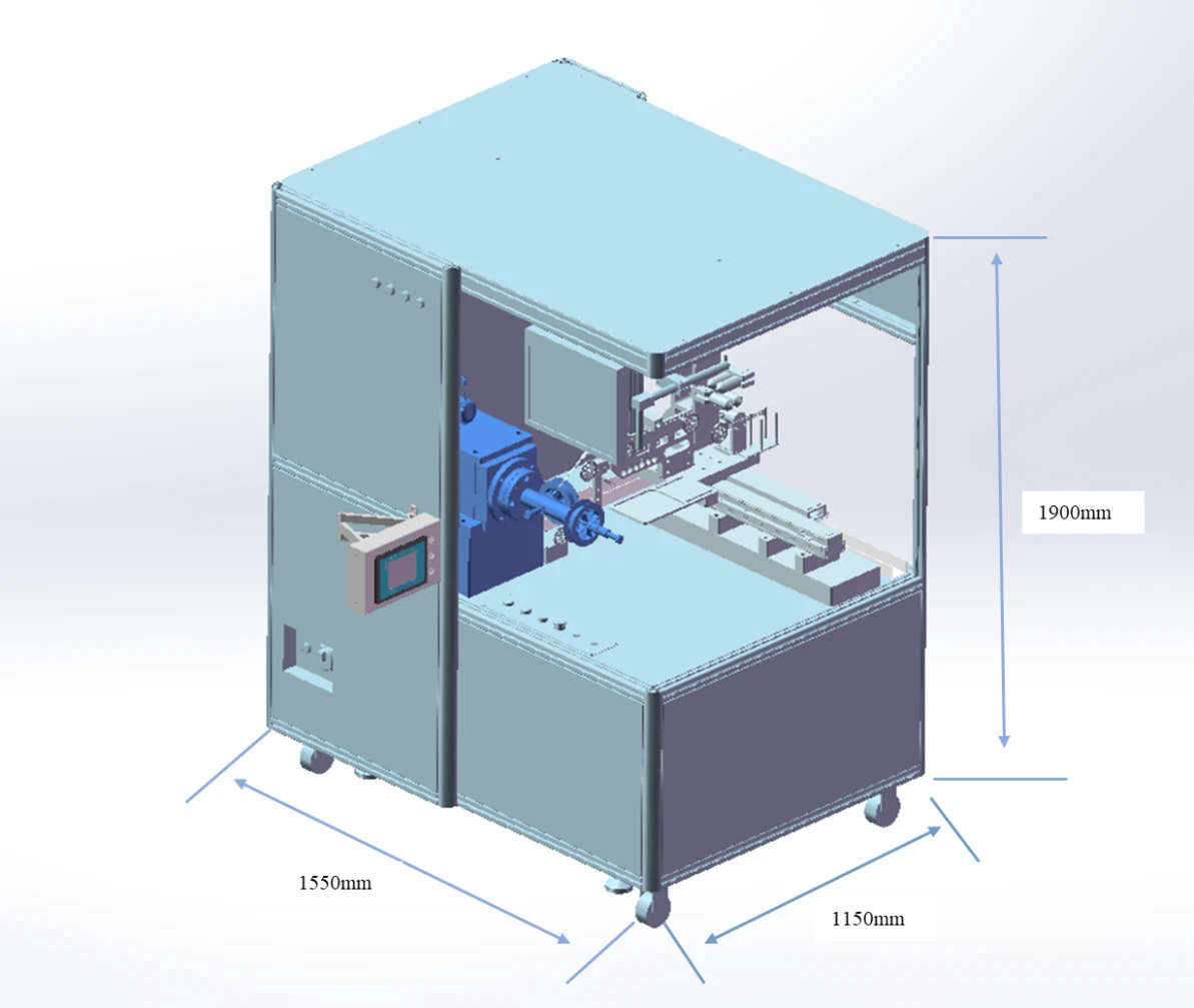
L 1500 × W 1150 × H 1900 |
Outline Drawing
Safety instructions
Before using the equipment, please carefully read the following safety section in order to ensure personal safety!!!!
WARNING
The power supply of this equipment is two-phase, three-wire 220V, pay attention to high voltage.
This equipment operates with rotating parts.
Failure to observe safe instructions may cause serious personal injury or property damage.
Only qualified personnel who thoroughly understand the following warnings, precautions and maintenance procedures should operate this equipment.
The key to safely using this equipment to produce qualified products lies in the proper mastery of the operation and maintenance process.
QUALIFIED PERSONNEL
Refers to people familiar with the operation and maintenance of this equipment and must have the following qualifications.
Trained and qualified in power supply, disconnection, cleaning, grounding, and marking of wiring and electrical equipment as required by safety regulations.
Trained in the proper maintenance and use of equipment as defined by safety regulations.
Trained in emergency care.
DANGER
Refers to death, serious injury or property damage that would have resulted if proper precautions had not been taken.
ATTENTION
Refers to the relevant parts of the product information and manuals that should be given high priority.
NOTES
Only qualified personnel familiar with this equipment and the information supplied with it are permitted to operate or service the equipment.
In the normal operation of the equipment, it is prohibited to touch the various production parts with your hands at will to prevent personal injury; to prevent damage to the machine.
Before performing intuitive overhaul and maintenance work, make sure that the AC power is disconnected; both the controller and the motor may carry dangerous voltages until the AC power is disconnected.
In the charged measurement, regardless of the circumstances are not allowed to touch the charged wiring; instrumentation measurement gear should be correct, to avoid incorrect gear and cause damage to the equipment phenomenon occurs.
Ensure that the equipment is well grounded and safe to operate.
After the equipment is energized, personnel without training, do not touch the various electrical components, terminals, etc., so as not to cause personal injury; such as the occurrence of line connection off phenomenon, please disconnect the power before processing.
When cleaning and maintaining the equipment, please turn off the power to carry out, do not operate with electricity, is strictly prohibited to clean with water.
Please strictly follow the equipment operation steps to ensure the production of qualified products; on maintenance of other notes, please contact us.
Requirements for Environment
In order to ensure the production of qualified products, and at the same time to extend the service life of the various components of the equipment, the user plant needs to have the following conditions:
Supply Voltage
Two-phase three-wire system 2×220V±10%, 50HZ±2% 3.5KW
Good grounding conditions must be provided (separate grounding device in accordance with international standards for personal protection and some degree of elimination of electromagnetic interference). With leakage and anti-static grounding.
Installation Environment
Temperature 20~25℃
Relative humidity 30 to 80% (no condensation)
Dust-free environment, cleanliness 100,000 grade
No corrosive or flammable gases
Well-ventilated premises, for hot air dissipation and personnel ventilation
No electromagnetic interference or harmful rays
Workshop illumination meets the requirements of precision instruments
The ground should be flat, bearing 500Kg / m2
Uses of Equipment and Features
RH16A multi-pole coil winding machine is the core equipment for making fiber coils of gyroscopes, and our company has the core technology of R&D and manufacturing. This winding machine can wind all kinds of symmetric or simple winding process of fiber coils, with easy operation, high precision automatic fiber laying, high precision automatic glue coating, high degree of automation, stable operation and so on.
Product Features
The whole machine adopts fully sealed welding structure. The bottom of the machine is equipped with universal Foma wheels, which is convenient for the movement of the equipment and also has shock absorption.
Meet the requirements of quadrupole, octupole, and hexadecapole fiber coils;
Precise automatic fiber laying during winding, capable of optical fibers with outer diameters of 100um, 135um, 165um, and 250um;
Real-time display of winding length, number of turns, number of layers, position of fiber laying, direction of spindle rotation, direction of fiber laying, tension and other information;
English measurement and control software HMI;
With spindle synchronized rotation function, customizable speed;
Manual real-time adjustment of rotational speed, rotational speed can be customized in the range of 0-80r/min, fiber pitch can be adjusted in real time;
Manually control the increase or decrease of the speed.
Can stop at any time, and manual control, with fiber reversing;
With in-line automatic gluing function;
With winding video monitoring, it can monitor the fiber winding situation in real time, and it is equipped with LCD display. The lens can be adjusted in XYZ three-dimensional direction;
Safety protection to prevent personnel from wrong operation causing damage to the equipment or products, such as winding tension protection, left and right limits of the coil winding tooling, and so on.
Main Technical Indicators
|
No. |
Item |
Unit |
Range |
|
1 |
Fiber Length Supported |
m |
≤10000 |
|
2 |
Tension control range |
g |
3 to 50 |
|
3 |
Tension control accuracy |
g |
±0.5(20r/min) |
|
4 |
Fiber Diameter Supported |
mm |
100-500 |
|
5 |
Turn Error |
turn |
≤0.01 |
|
6 |
Length Error |
≤3 per cent |
|
|
7 |
Spindle Radial Runout |
mm |
≤0.02 |
|
8 |
Spindle Axial Runout |
mm |
≤0.02 |
|
9 |
Fiber Laying Straightness |
mm |
≤0.01 |
|
10 |
Fiber Laying Repeatability |
mm |
±0.01 |
|
11 |
Winding speed |
r/min |
0 to 80 |
|
12 |
Fiber Laying Movement |
mm |
200 |
|
13 |
Winding Fiber Coil Outer Diameter |
mm |
20 to 250 |
|
14 |
Diameter of Spindle for Fixing Coil Skeleton |
mm |
φ15, φ10 |
|
15 |
Width of Pay-off Spool |
mm |
40 to 80 |
|
16 |
Spindle Rotary Diameter |
mm |
≥200 |
|
17 |
Spindle Center Height |
mm |
≥300 |
Equipment Composition and Working Principle
Equipment Composition
|
Fiber take-up device |
1 set |
|
Fiber laying device |
1 set |
|
Fiber pay-off device |
1 set |
|
Tension sensing device |
1 set |
|
Coil skeleton fixing spindle |
1 set |
|
Fiber guiding device |
1 set |
|
Automatic gluing device |
1 set |
|
Industrial control computer and display unit |
1 set |
|
HD camera and display unit |
1 set |
|
Standard fiber rewinding spool |
2 pcs |
Machine Structure
The external dimension of the equipment is 1550mm (L) x 1150 (W) x 1900mm (H); the bottom is installed with movable heavy-duty Footmaster wheels and equipped with a horizontal adjustment mechanism, which facilitates the movement of the equipment as well as horizontal positioning.
The spindle is the core component to ensure the main technical index of the coil winding machine. The spindle adopts high-precision spindle with rotary runout ≤0.02mm and is equipped with servo motor to drive the spindle to meet the requirements of speed and position.
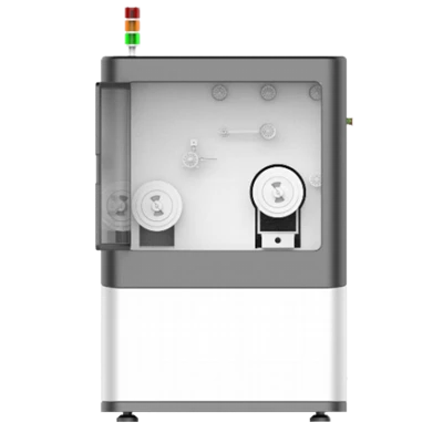
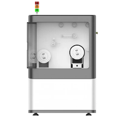
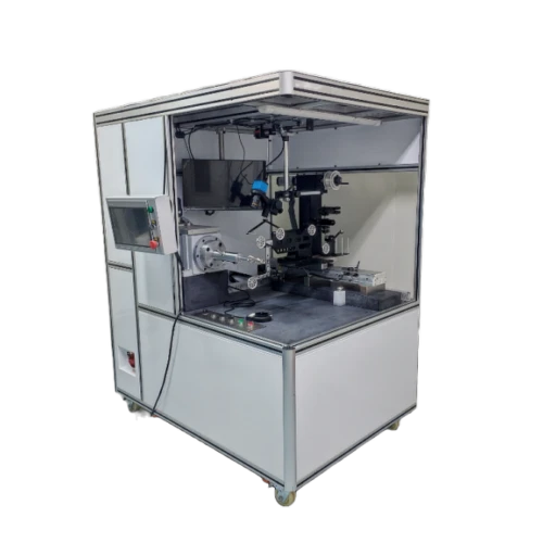
The device profile is shown in the figure.
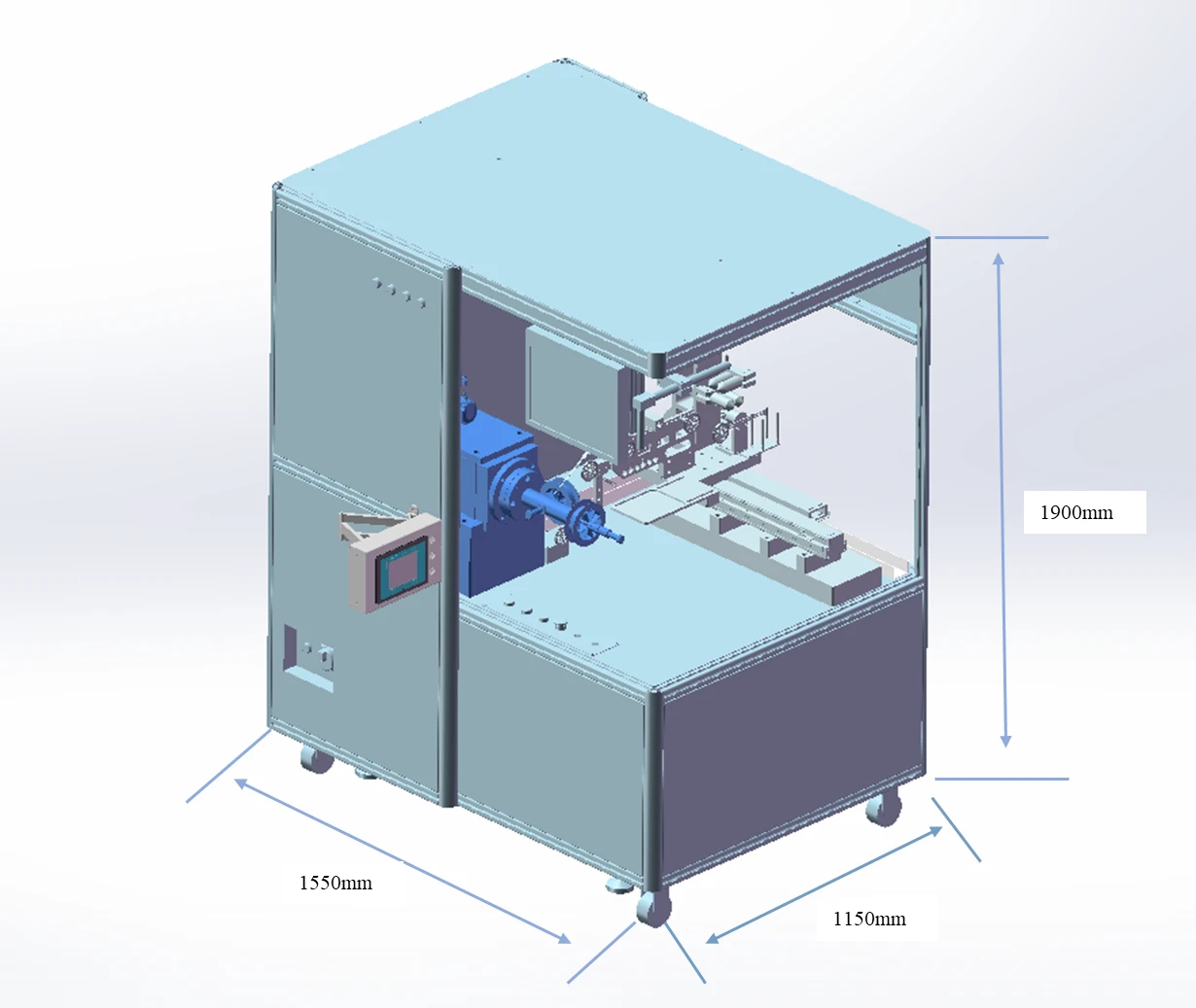
Figure 1: Product Picture
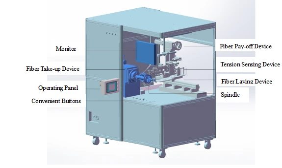
Figure 2: Product Form Factor II
Fiber take-up Device
Precision spindle
The spindle is mainly composed of spindle motor + original imported high-precision gear motor:
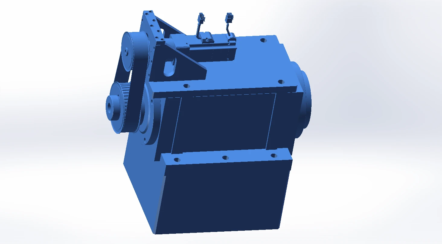
Figure 3: Precision spindle
Structure and working principle
This device is used in the fiber take-up of coil winding, and mainly completes the rotary function of fiber take-up. The device is powered by the main spindle motor, and the user can set the rotating speed and rotating direction of the motor on the operating panel. The motor rotation is transmitted to the main spindle through the high-precision imported gear motor and synchronous belt, and the main spindle drives the fiber coil to rotate at a uniform speed. In the coil winding process, the fiber coil is set on the skeleton fixed section and the fiber pay-off spool is set on the spool fixing section.
Skeleton Mounting Parts
The skeleton mounting parts are stepped and divided into a skeleton fixing section and a spool fixing section:
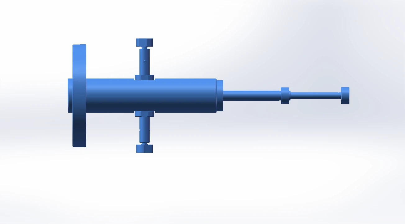
Figure 4: Skeleton mounting components
Fiber Take-Up Device
The fiber take-up device mainly consists of precision main spindle + skeleton mounting parts + skeleton fixing section:
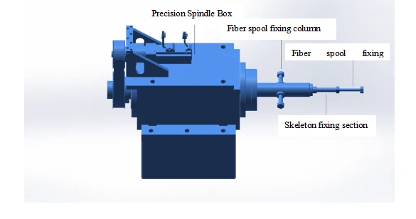
Figure 5: Fiber take-up System
Precision Fiber Laying Device
Precision Fiber Laying Device mainly consists of fiber laying motor + high precision guide rail module:
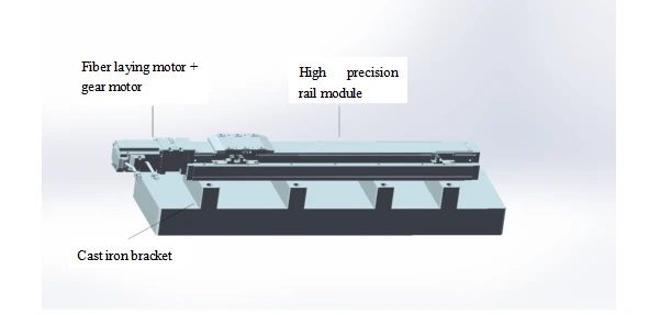
Figure 6: Precision Fiber Laying
Structure and working principle
This device mainly completes the precision movement of fiber laying, using servo motors connected to highly speed reduction ratio gear motor, which will drive the working platform to move by the high precision rail. During fiber winding, according to the fiber take-up speed, fiber diameter, precisely calculating the movement of fiber laying, so that the movement of precision sliding rail will be the same as the speed of fiber laying, to achieve consistency, maintain balance, achieving precision fiber laying. Fiber pay-off device and tension sensor are fixed on the fiber laying system, they will stay relative static with the fiber laying system while working.
Fiber Pay-off Device
The fiber pay-off device mainly consists of fiber pay-off motor + original imported high-precision gear motor:
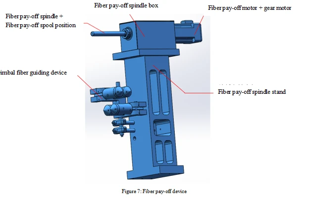
Structure and working principle
This device mainly controls the precision movement of fiber pay-off, using servo motor connected to the high reduction ratio gear motor, which will drive the fiber pay-off spindle by a coupling. During fiber winding, according to the fiber take-up speed, tension, precisely calculating the movement of fiber pay-off, adjusting at any time, to ensure that the fiber will be winded by a stable tension onto the skeleton; equipped with a gimbal guide device, so that the fiber does not torsion at any angle, reduce additional stress because of torsion while winding.
Tension Sensing Device + Fiber Guiding Device
Tension sensing device mainly consists of tension sensor + fiber guiding wheel:
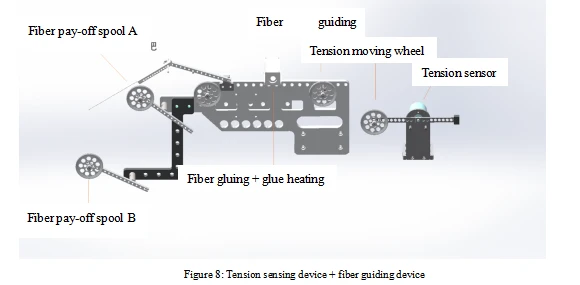
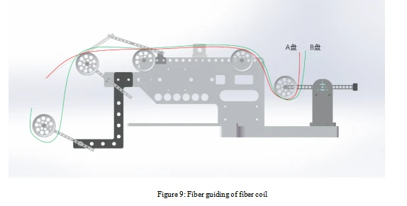
Structure and working principle
The tension sensing device + fiber guiding device are fixed on the precision rail of the fiber laying system.
Tension sensing device has a circular fiber guide wheel, fixed on a swing arm which can be rotated. There is a moving wheel that used to stabilize the tension. In the center of the swing arm, there is a tension sensor, timely feedback the position of the moving wheel to the PLC control system, the system in accordance with the received position of the moving wheel to adjust the speed of fiber pay-off.
When the fiber laying on the skeleton is not ideal, fiber appears to be stacked or loose, which needs to be retracted, the direction of the motor for fiber take-up, fiber pay-off and fiber laying can be controlled by the touch panel to reach an ideal situation.
In the winding process, if there is a need to replace the spool, according to Figure 9 Fiber guiding of fiber coil, directly put the corresponding spool on the fiber pay-off spindle, to achieve rapid spool change.
Gluing Device
The gluing device is mainly made of brush mounting hole and heater.
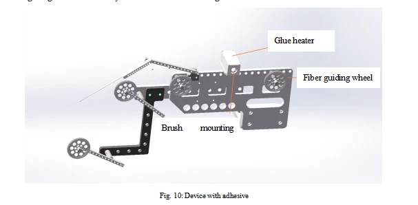
Structure and working principle
The gluing device is fixed on the fiber guiding device.
The glue box on the gluing device has a round hole, under normal circumstances, install the brush on the outlet of dispensing syringe, the syringe is installed in the round hole, the optical fiber goes through the center of the brush. Amount of glue can be controlled by adjusting syringe glue output. In addition, there is an electric heating device on the bottom, temperature of the glue can be controlled, to avoid the glue getting solid during long time use.
Precision Platform
Precision platform is mainly composed of marble platform as well as casting support frames:
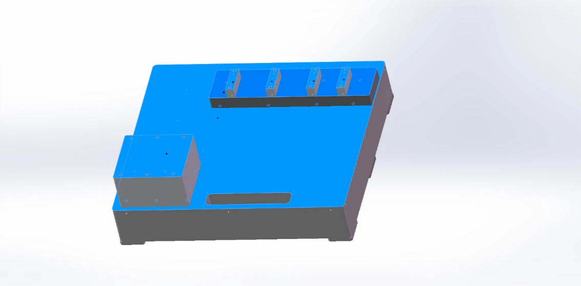
Figure 11: Precision platform
Structure and working principle
This device mainly completes the task of supporting and adjusting the height of each part, using a combination of marble platforms and casting parts; marble platforms to ensure the flatness of the operation desktop, casting parts to ensure that the platform does not occur deformation during long time use.
Electronic Control System Program
The electric control system is an important part of the multi-pole fiber winding machine to realize the motion control and finally achieve the technical performance index. On the basis of the understanding of its technical performance indexes and the requirements for use, we put forward the technical scheme of the electric control system of the multi-pole fiber optic winding machine, which includes the following main contents:
The main components of the electronic control system;
Tension control system;
Precision fiber laying system;
Control system synthesis;
Security protection for system operation.
The program fully considered mature and advanced technology. The control system adopts position of the closed-loop digital composite control structure combined with the mainstream industrial control PC computer and Mitsubishi series PLC multi-axis motion axis control system. Friendly graphical human-machine interface provides flexible operation and display in the winding process; high-precision servo motor system with the position of the encoding reference signal of the optoelectronic incremental shaft encoder as a measurement of each axis of the movement of the feedback element; PLC axis motion controller and the control computer The PLC axis motion controller and control computer are configured with RS232 to communicate with the upper computer to realize control; the computer software is based on WINDOWS operating system with function expansion capability.
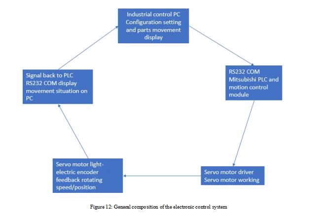
The control computer is the main part of the electronic control system, which accomplishes various control operations of the ring-winding machine, data input and output and the management functions of each functional template, as well as equipment fault monitoring and safety protection.
Mitsubishi PLC is the core of each axis motion control, through the drive unit with each axis, motion mechanism, axis angle measurement and feedback unit constitutes a position closed-loop system, to achieve the coordinated motion control of each axis, and provide cycle measurement circuit for speed calibration measurement and provide fixed-angle synchronized pulse output. The control computer also accomplishes various human-machine interface management functions of the equipment, such as user data input, equipment real-time data output and motion trajectory curve display.
High-Definition Camera and Display Unit
The display unit is divided into two parts, the first part is the camera display unit, the second part is the human-computer interaction interface, displaying the machine's operating functions and parameters, besides, the convenient operation buttons can also operate the coil winding machine:
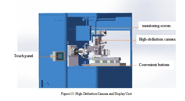
Industrial Control System
Industrial control system consists of industrial control machine + PLC control system + server, the human-machine interface control system is installed in the industrial control machine, together with PLC controller, making the entire industrial control system, complete each motion of the equipment.
The HMI control system interface is as follows:
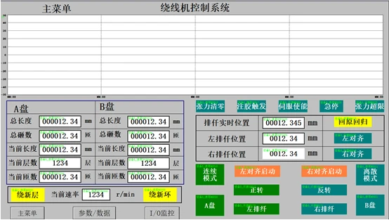
Figure 14: Industrial control system control interface
Equipment Operation
Preparation
Open the air switch (lower left corner) of the main power, press the power button on the touch panel, at this time the machine is powered on, the machine enters the working state.
Check if there is abnormal alarm on the operation interface
Examine each part of the machine for any abnormalities that may affect the normal operation of the machine;
Inspect all parts of the machine for abnormalities that affect safety.
Running Operation
Configuration
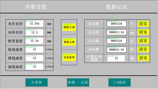
Figure 15: Parameter setting interface
|
Item |
Description |
|
Fiber diameter |
Setting the currently used fiber diameter |
|
Coil inner diameter |
Setting the coil inner diameter of the currently used skeleton |
|
Skeleton width |
Setting the coil inner width of the currently used skeleton |
|
Fiber take-up speed |
Setting the basic speed of fiber take-up axis |
|
Fiber laying speed |
Setting the basic speed of fiber laying speed |
|
Fiber pay-off speed |
Setting the basic speed of the fiber pay-off axis |
|
Total coils |
Recording the total coils that have been winded |
|
Total length |
Recording the total length |
|
Total layers |
Recording the total layers |
|
Total turns |
Recording the total turns |
|
Start-up turns of glue injection |
Glue will be injected every certain turn |
|
Camera left/right move |
Click to move the position of the camera |
|
Equipment lighting |
Click to turn on/off the light in the machine |
The parameters of coil winding (e.g. fiber ring skeleton width, skeleton diameter, fiber diameter) are set through this interface as follows:
Enter the HMI - Parameter/Data button to set up.
Control
The operation of this equipment is mainly on the human-machine interface, and the location of each operation key is shown in the following figure:
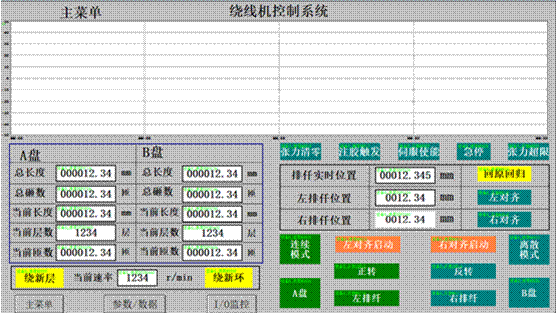
Figure 16: Control Interface
|
Item |
Description |
|
Menu |
Operation monitoring interface (power-on interface) |
|
Tension display |
Current encoder tension display of fiber |
|
Spool A data |
Record the data generated when spool A is running. |
|
Spool B data |
Record the data generated when spool B is running. |
|
Current rate |
Current winding spindle speed (r/min) |
|
Current location of fiber laying |
Current position of the fiber laying spindle |
|
Left fiber laying Position |
This means the Position calculated by the system based on the current width of the skeleton |
|
Right fiber laying position |
This is the button for setting the starting position of the fiber laying |
|
New layer |
Finish winding the current layer. Click the Wind New Layer button. The current length and number of turns are cleared, and the current layer increases by 1. |
|
New coil |
The current coil is finished. Click new coil. All data of spool A and B are cleared and counting starts again. |
|
Clear tension |
Clear the current encoder coordinate value |
|
Glue injection trigger |
Glue injection signal– setting the parameters of glue injection |
|
Servo enable |
This means the servo is enabled |
|
Emergency stop |
This means emergency stop. |
|
Tension overload |
This means the tension is overloaded. |
|
Return to origin |
This is the button for Fiber laying axis goes returns to origin when the machine is stopped or in manual mode. Doesn't work in automatic mode. |
|
Left alignment |
This means the left alignment function starts |
|
Right alignment |
This means the right alignment function starts |
|
Continuous mode |
This is the button for three axes work together |
|
Separate mode |
This is the button for three axes work separately |
|
Left alignment startup |
This is the button for starting three axes working together |
|
Right alignment startup |
This is the button for starting three axes working separately |
|
Forward rotate |
This means the winding axis is rotating forward |
|
Backward rotate |
This means the winding is rotating backward |
|
Spool A |
This the button for executing program of spool A, and recording spool A data |
|
Spool B |
This the button for executing program of spool B, and recording spool B data |
|
Fiber laying leftward |
This is the button for laying fiber leftward |
|
Fiber laying rightward |
This is the button for laying fiber rightward |
|
Menu |
Access to the main operator interface button |
|
Parameters/data |
This is the button for entering the parameter setting/data logging interface |
|
I/o monitoring |
Access to PIC input/output I/O |
Tension control
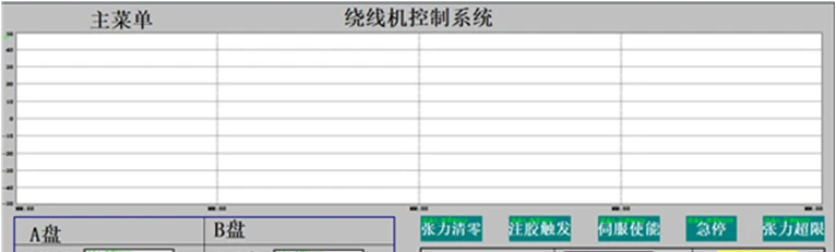
Control Panel
No.1 is to adjust the speed of the winding spindle
No.2 is to change the rotating direction: forward or backward
No.3 is to change the direction of fiber laying: leftward or rightward
No.4 is to slightly change the direction of fiber laying: leftward or rightward
No.5 is to start the machine
No.6 is to stop the machine
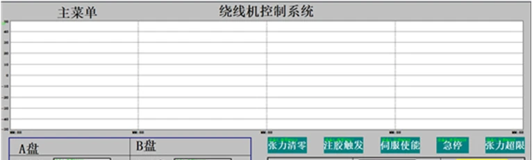
Fault Alarm and Remove
Fault Alarm
When the machine is running automatically or manually, a warning message appears on the operation monitor, which indicates that the machine is in a fault alarm state and puts the machine in a suspended state, while the interface usually displays a fault message.
Alarm Status Remove
According to the fault information on the operation interface or through observation to determine the fault, after the fault is solved, the alarm is removed, the machine restores the original operating state.
Emergency Stop
When an emergency situation requires an immediate stop, press the red Emergency Stop button immediately.
At this time, the machine stops immediately and all operations do not work, there will be no warning in the operation monitoring. After troubleshooting, rotate
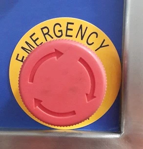
the Emergency Stop button so that it pops out, and press the reset button before the problem is solved.
Operation Precautions
Please keep the operator away from the equipment body when the equipment is running to avoid personal injury;
Do not operate the machine at high speeds (speeds of 300m/min and above) for optical fibers with diameters smaller than 170um (including 170um). This is because small diameter optical fibers are easily damaged at high speeds. It is recommended to control the speed within 200m/min.
Do not turn off the power while the machine is in normal operation as this may cause significant damage to the machine;
Please check each wearable and fragile part of the machine regularly;
Please perform timely maintenance on all moving parts, such as line guide bearings, guide wheel small bearings and other parts;
Please draw a warning line range where the machine is to be used to avoid injury to personnel caused by fiber breakage during high-speed operation;
Periodic Maintenance Schedule
|
Type |
Frequency |
Content |
|
Daily |
Everyday |
Check operating temperature, humidity, dust, foreign matter, etc. |
|
Check abnormal vibration and noise |
||
|
Check power supply voltage |
||
|
Check whether there is a strange odor |
||
|
Check the cleanliness of the front of the servo drive, connectors |
||
|
Check the wires |
||
|
Check connection parts with equipment and deviation of core feet |
||
|
Check there is no foreign objects embedded in the load section |
||
|
Check guide wheels are clean, smooth and burr-free, and stable |
||
|
Check the tension control system is flexible and no stuttering |
||
|
Use clean and dry dust-free gauze to wipe the surface plane of the machine, the surface of the slide table, the skeleton fixed parts, guide fiber wheel and other small parts need to use tweezers to clip the alcohol cotton cleaning |
||
|
Periodically |
Weekly |
Skeleton fixing parts rails, sleeves are lubricated with sewing machine oil. |
|
Monthly |
Tightening of fiber pay-off bearing screws |
|
|
Tightening of fiber take-up bearing screws |
||
|
Tightening of line guide fixing screws |
||
|
Guide wheel bearing positioning in the same plane |
||
|
Lubrication of each working bearing |
||
|
Yearly |
Whether the wiring of the drive is loose or not |
|
|
Check for loose connection plugs between servo motor and drive |
||
|
Whether the grounding wire of each device is secure |
||
|
Rotating bearing inspection |
Common Failures and Handling Methods
|
No. |
fault |
cause |
Treatment |
note |
|
1 |
No power after the equipment mains plugged in |
No power to the mains plugs socket; Air switch Q1 in the electrical cabinet is not closed; The power button on the operation panel is not pressed; |
Turn on power to the main power outlet; Close the Q1 air switch in the electrical cabinet; Press the power button on the operation panel; |
be careful of electrocution |
|
2 |
The equipment has power, the servo drive display panel of fiber laying, fiber pay-off, fiber take up, etc. has no display |
Servo drive air switch Q1 to Q7 is not closed for fiber laying, fiber pay-off and fiber take-up. |
Close air switches Q1 to Q7 in the electrical cabinet. |
be careful of electrocution |
|
3 |
PLC module not working |
PLC module is not powered up PLC mode is "STOP". |
Close air switch Q9 Switch the PLC mode to "RUN" |
be careful of electrocution |
|
4 |
The left and right "OFF/ON" buttons do not light up. |
The tension is too high or too low, or the upper/lower tension protection limit is set too low. |
Manually adjust the tension so that the tension is within the upper/lower limit of the tension protection value or set the protection value higher. |
be careful of electrocution |
|
5 |
Alarm box prompts "left limit or right limit" alarm indicator lights up |
Line guide reaches limit position, automatic machine protection |
An emergency stop button needs to be pressed to reset the guide rail by manually turning the guide rail screw when a guide rail left/right limit alarm occurs. Keep the row of wire base away from the left/right limit protection switch. |
Power must be turned off |
Hot Tags: rh16a fiber coil winding machine, China rh16a fiber coil winding machine manufacturers, factory