Description
Key Features
- Adjustable curing temperature
- Rotary product curing
Applications
- Fiber coil
- Other curing applications
Product Introduction
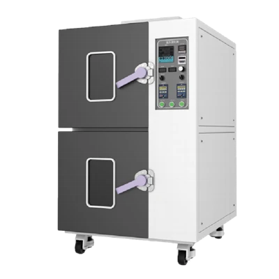
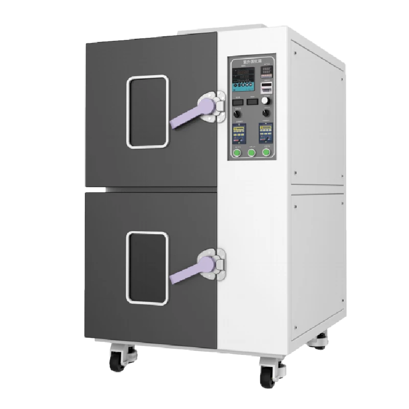
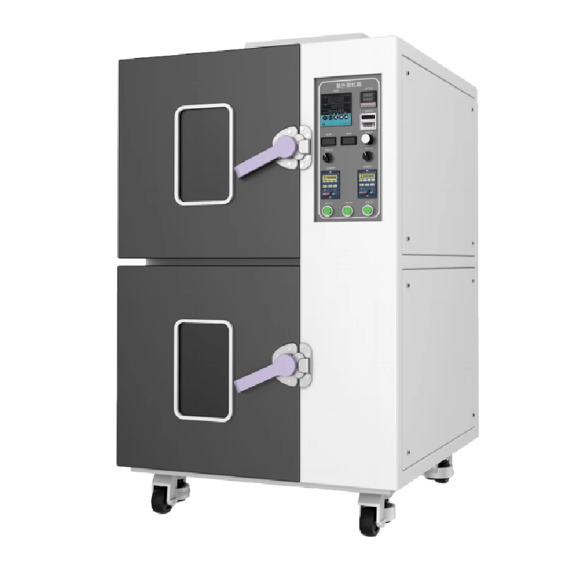
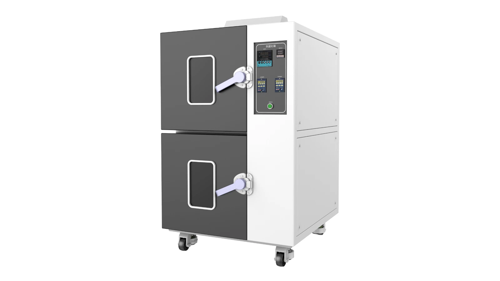
Company GR02 thermal curing chamber is primarily used for curing wound fiber coils. Through high-temperature heating, the adhesive bonds the fiber to the spool.
Unique Technology
Company is a high-tech enterprise with full closed-loop capabilities from fiber winding equipment and coils to FOGs, fiber/MEMS inertial products, IMU circuits, software, and test equipment. End-to-end process control improves quality and reduces costs. Operating under ISO9001 with strict processes, it ensures product reliability and consistency.
Parameters
GR02 Thermal Curing Chamber Specifications
|
Parameter |
Specifications |
|
Heating Chamber System |
|
|
Power Supply Voltage |
220V 50HZ |
|
Chamber Dimensions |
500 × 400 × 500 (W × D × H mm) |
|
Rated Power |
2000W |
|
Temperature Fluctuation |
±1℃ |
|
Temperature Range |
Room temp. +10°C–200°C (adjustable); 60°C–200°C under light (adjustable) |
|
Heating Rate |
Avg. 1–5°C/min (adjustable) |
|
Product Rotation System: consists of rotary motor and stepless speed controller |
|
|
Motor Power |
100 W × 1 |
|
Motor Speed |
1–20 RPM (adjustable, speed range selectable) |
|
Motor Shaft Dimensions |
50 mm × M12 internal thread |
|
Rotation Shaft |
1 shaft, custom |
|
Speed Controller |
Digital stepless speed controller |
Introduction
GR02 Thermal Curing Chamber is mainly used for curing the finished winding fiber coils, through high temperature heating to make the glue fixed with the fiber and skeleton.
Main Technical Data
Curing Chamber Heating System:
Power supply voltage: 220V 50HZ
Chamber inner size: 500 * 400 * 500 (width * depth * height mm)
Rated power: 2000W
Temperature fluctuation: ±1°C
Temperature range: room temperature +10°C-200°C (adjustable), 60°C-200°C under light (adjustable)
Temperature rising speed: average 1~5℃/min (adjustable)
Rotating System: consists of rotary motor, infinitely variable speed controller.
Motor power: 100W*1pc
Motor speed: 1r~20r/min (adjustable, rotational speed range selectable)
Motor shaft length: 50mm*M12 internal threads
Rotary shaft: 1pc Customized
Governor: digital display infinitely variable governor
Equipment Composition
Curing chamber heating system
Rotating system
Note: For the specific contents of the equipment composition, please refer to the technical annexes of the sales contract, and the indexes mentioned in this manual are all within the scope of the equipment sales contract constraints.
Installation Instructions
The flooring where the equipment is installed is required to be level.
Only qualified electrical personnel who are familiar with the electrical schematic connection diagrams of this equipment in advance are allowed to carry out the electrical connection installation work of this equipment.
The internal wiring of this equipment has been completed before leaving the factory, before normal operation, please check the wiring carefully. Prevent the joints from loosening during transportation due to the bumps of transportation, causing the equipment not to work properly.
Installation Place
In order to ensure the production of qualified products, and at the same time to extend the service life of the various components of the equipment, the user plant needs to have the following conditions:
Power Supply
Single-phase three-wire system: single-phase three-wire 220V (±10%), 50Hz, 2.0KW
Users need to provide good grounding conditions for the equipment (independent grounding devices designed in accordance with international standards, personnel protection and a certain degree of elimination of electromagnetic interference.
Installation Environment
Temperature: 0-30°C
Dust-free, dusty environment
Relative humidity in the range of 20-90% (no condensation)
No corrosive or flammable gases
Well-ventilated premises to facilitate heat dissipation from the equipment
Safety Instructions
Before the user touches this equipment for the first time, please read the following safety section carefully for personal safety!!!!
 Warning!
Dangerous voltages and rotary movements are present in some parts of this equipment during operation.
Failure to observe safe operation may cause serious personal injury or property damage.
Only qualified personnel who first thoroughly understand the following warnings, precautions and maintenance procedures should operate this equipment or work around it.
The key to safely using this equipment to produce acceptable products is proper operation and maintenance procedures.
Qualified Personnel
Refers to personnel familiar with the operation and maintenance of this equipment and must have the following qualifications:
Personnel trained and qualified in power supply, disconnection, cleaning, earthing, marking of wiring and electrical equipment in accordance with safety regulations.
Personnel trained in the proper maintenance and use of protective equipment in accordance with safety regulations.
Personnel trained in emergency care.
 Danger!
Refers to death, serious personal injury or material property damage that could have resulted if proper precautions had not been taken.
 Attention!
Refers to relevant parts of product information and manuals that should be given high priority.
Maintenance Precautions
Only qualified personnel familiar with this equipment and the information supplied with it are permitted to operate or service the equipment.
All panels and doors of the equipment must be closed during normal operation, and it is prohibited to touch the various production parts with hands at will to avoid personal injury.
Before performing visual inspection and maintenance work, make sure that the AC power supply is disconnected; before disconnecting the AC power supply, both the controller and the motor may carry dangerous voltages, even when the controller contactor is disconnected, which need to be released from the charge before operation (the best way is to disconnect the power supply and leave it for a period of time, waiting for the charge to be released).
Under no circumstances should energized wiring be touched during energized measurements.
Ensure good grounding conditions and safe operation of the equipment; due to the use of more controllers and other components, this equipment may carry high induced voltages, which must be safely grounded.
When working on energized parts, it is important to stand on an insulating surface, i.e. to ensure that there is no direct contact with the earth.
After the equipment is energized, untrained and qualified personnel, do not touch the original electrical appliances, terminals, etc., so as not to cause personal injury; such as the occurrence of line connecting line off the phenomenon, please disconnect the power and then deal with it.
Follow the instructions carefully and observe the precautions concerning "Danger" and "Warning".
When cleaning the equipment, please turn off the power, do not wipe with electricity, and strictly prohibit rinsing with water.
Please strictly follow the equipment operation steps to ensure the production of qualified products; for other notes on maintenance, please contact us.
Equipment Operation
Operating Procedure
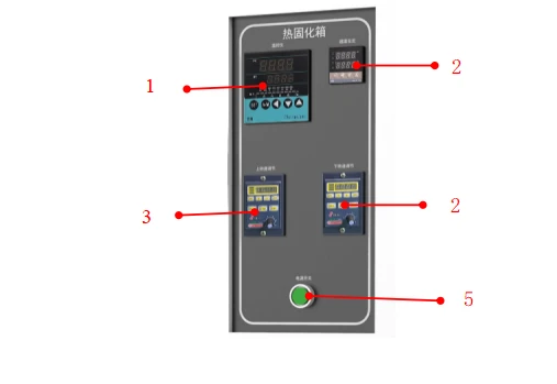
No. 1 is temperature controller of the upper temperature chamber, this controller can be set for a number of different temperatures and different time, with memory function, automatically record the last set temperature program. Temperature controller default over-temperature setting is 3 degrees, when the SV temperature on the instrument is over than the PV temperature of 3 degrees, the temperature controller will automatically cut off the heating and internal circulation fan power supply, when the temperature comes down, the disconnected switch will be closed, into the normal heating state. Because of the curing characteristics of the fiber coil glue, it is recommended that the temperature controller set the maximum temperature is not greater than 45 degrees. Before operating this temperature controller, be sure to check the temperature controller's manual.
No. 2 is the secondary temperature protection controller for the upper chamber, its principle is similar to No. 1, when No. 1 controller over-temperature protection fails or the instrument fails, No. 2 controller as a secondary protection device will be activated, No. 2 controller will be activated to disconnect the heating, at the same time activates the exhaust fan behind the equipment, to draw away the hot air inside the chamber, quickly cool down the chamber. The over-temperature protection value of this controller is recommended to be set at 50 degrees to 55 degrees. Before operating the temperature controller, be sure to check the manual of the temperature controller.
No. 3 is the rotary shaft speed controller for the upper chamber, it can set start, stop, forward rotate (FWD), reverse (REV), automatically rotate after power-on. The black knob is to adjust the rotary shaft, MODE for the menu key, ↑ key for increase, ↓ key for decrease, ENTER is the confirmation key. On the LCD screen of the speed controller, the current real-time speed of the rotary shaft and the current direction of the rotary shaft are displayed. Each time in the curing test, just press REV or FWD to start the rotary axis.
No. 4 is a rotary shaft speed controller for room temperature curing in the lower chamber, which operates in the same manner as controller No. 3.
No. 5 is the power start button of the heat curing chamber. After the button is pressed, the green panel is concave, means power on, press it again, the green panel is back to flat and the green light be turned off, means power off.
Hot Tags: gr02 thermal curing chanber, China gr02 thermal curing chanber manufacturers, factory