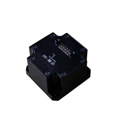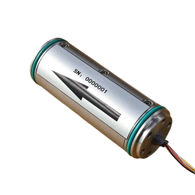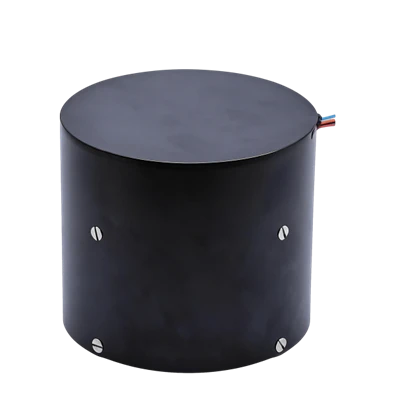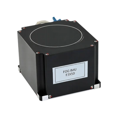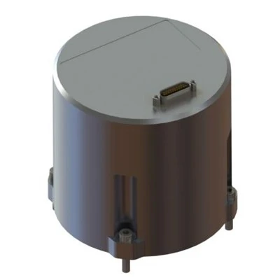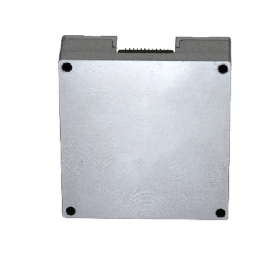
MSU204A MEMS Inertial Measurement Unit
SPI serial communication compatible
Built-in temperature sensor
Pin-to-pin compatible with ADIS16488A
Description
Main Features
- Full-temperature calibration and compensation from -40 ℃ to +80 ℃ (for gyroscopes and accelerometers)
- SPI serial communication compatible
- Built-in temperature sensor
- Pin-to-pin compatible with ADIS16488A
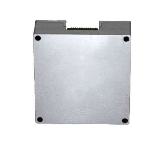
Application Fields
 Vibration suppression and attitude control of industrial equipment
 Automatic control systems
 Gimbal stabilization and control
Product Overview
MSU204A MEMS is a compact, high-precision 9-axis inertial measurement unit (IMU), designed for high-precision navigation, control and dynamic measurement of carriers. The MSU204A series inertial measurement module integrates MEMS gyroscopes, MEMS accelerometers and MEMS magnetometers within a single housing. Adopting highly reliable MEMS sensors, it can accurately measure angular rate, acceleration and magnetic field information of moving carriers under harsh environments, making it a general-purpose device for industrial applications.
Unique Technology
Company is a high-tech enterprise with full closed-loop capabilities from fiber winding to FOGs, fiber/MEMS inertial products, IMU circuits, software, and test equipment. End-to-end process control improves quality and reduces costs. Operating under ISO9001, it ensures reliability and consistency.The MSU204A inertial measurement module adopts an aluminum alloy housing, which is lightweight with high structural strength and excellent anti-vibration & anti-shock performance.
MSU204A MEMS Inertial Measurement Unit
MSU204A MEMS Inertial Measurement Unit Performance Parameter
|
Parameter Group |
Parameter |
Test Condition |
Min. |
Typical |
Max. |
Unit |
|
Gyroscope |
Measurement Range |
500 |
+500 |
°/s |
||
|
Full-temperature Bias |
100 |
300 |
°/h |
|||
|
Bias Stability |
10s smoothing |
5 |
°/h |
|||
|
Bias Instability |
Allan variance |
1 |
°/h |
|||
|
Bias Repeatability |
Constant temperature |
1.5 |
5 |
°/h |
||
|
Angular Random Walk |
0.1 |
°/√h |
||||
|
Scale Factor Non-linearity |
25 |
100 |
ppm |
|||
|
Cross-coupling Error |
0.001 |
Rad |
||||
|
Bandwidth |
200 |
Hz |
||||
|
Accelerometer |
Measurement Range |
-16 |
+16 |
g |
||
|
Full-temperature Bias |
1 |
3 |
mg |
|||
|
Bias Stability |
10s smoothing |
0.03 |
0.1 |
mg |
||
|
Bias Instability |
Allan variance |
0.01 |
0.03 |
mg |
||
|
Bias Repeatability |
Constant temperature |
0.03 |
0.1 |
mg |
||
|
Velocity Random Walk |
0.01 |
0.03 |
m/s/√h |
|||
|
Scale Factor Non-linearity |
±1 g input |
100 |
200 |
ppm |
||
|
Cross-coupling Error |
0.001 |
Rad |
||||
|
Bandwidth |
200 |
Hz |
||||
|
Magnetometer |
Measurement Range |
-8 |
+8 |
Gs |
||
|
Resolution |
200 |
μGs |
||||
|
Noise Density |
50 |
μGs |
||||
|
Bandwidth |
200 |
Hz |
||||
|
Barometer |
Measurement Range |
300 |
1100 |
mbar |
||
|
Total Error |
4.5 |
mbar |
||||
|
Absolute Error |
1.5 |
mbar |
||||
|
Non-linearity |
0.1 |
%FS |
||||
|
Resolution |
0.1 |
mbar |
||||
|
Reliability |
MTBF (Mean Time Between Failures) |
20000 |
h |
|||
|
Continuous Operating Duration |
120 |
h |
||||
|
Note: Typical values represent 1σ statistical results of multiple sample tests. |
||||||
Product Overview
Product Introduction
MSU204A MEMS is a compact, high-precision 9-axis inertial measurement unit (IMU), designed for high-precision navigation, control and dynamic measurement of carriers. The MSU204A series inertial measurement module integrates MEMS gyroscopes, MEMS accelerometers and MEMS magnetometers within a single housing. Adopting highly reliable MEMS sensors, it can accurately measure angular rate, acceleration and magnetic field information of moving carriers under harsh environments, making it a general-purpose device for industrial applications.
Key Features
- 3-axis digital gyroscope, measurement range ±500 °/s
- 3-axis digital accelerometer, measurement range ±16 g
- Digital barometric pressure sensor, range 300 mbar ~ 1100 mbar
- Full-temperature calibration and compensation from -40 ℃ to +80 ℃ (for gyroscopes and accelerometers)
- SPI serial communication compatible
- Built-in temperature sensor
- Compact size and lightweight
- Pin-to-pin compatible with ADIS16488A
Application Fields
- Vibration suppression and attitude control of industrial equipment
- Automatic control systems
- Robot control
- Gimbal stabilization and control
- Instruments and meters
Electrical & Performance Specifications
Table 1 Performance Parameters of MSU204A Inertial Measurement Module
|
Parameter Group |
Parameter |
Test Condition |
Min. |
Typical |
Max. |
Unit |
|
Gyroscope |
Measurement Range |
-500 |
+500 |
°/s |
||
|
Full-temperature Bias |
100 |
300 |
°/h |
|||
|
Bias Stability |
10s smoothing |
5 |
°/h |
|||
|
Bias Instability |
Allan variance |
1 |
°/h |
|||
|
Bias Repeatability |
Constant temperature |
1.5 |
5 |
°/h |
||
|
Angular Random Walk |
0.1 |
°/√h |
||||
|
Scale Factor Non-linearity |
25 |
100 |
ppm |
|||
|
Cross-coupling Error |
0.001 |
Rad |
||||
|
Bandwidth |
200 |
Hz |
||||
|
Accelerometer |
Measurement Range |
-16 |
+16 |
g |
||
|
Full-temperature Bias |
1 |
3 |
mg |
|||
|
Bias Stability |
10s smoothing |
0.03 |
0.1 |
mg |
||
|
Bias Instability |
Allan variance |
0.01 |
0.03 |
mg |
||
|
Bias Repeatability |
Constant temperature |
0.03 |
0.1 |
mg |
||
|
Velocity Random Walk |
0.01 |
0.03 |
m/s/√h |
|||
|
Scale Factor Non-linearity |
±1 g input |
100 |
200 |
ppm |
||
|
Cross-coupling Error |
0.001 |
Rad |
||||
|
Bandwidth |
200 |
Hz |
||||
|
Magnetometer |
Measurement Range |
-8 |
+8 |
Gs |
||
|
Resolution |
200 |
μGs |
||||
|
Noise Density |
50 |
μGs |
||||
|
Bandwidth |
200 |
Hz |
||||
|
Barometer |
Measurement Range |
300 |
1100 |
mbar |
||
|
Total Error |
4.5 |
mbar |
||||
|
Absolute Error |
1.5 |
mbar |
||||
|
Non-linearity |
0.1 |
%FS |
||||
|
Resolution |
0.1 |
mbar |
||||
|
Communication Interface |
SPI Clock Frequency |
10 |
MHz |
|||
|
UART Baud Rate |
9.6 |
460.8 |
921.6 |
kbps |
||
|
Electrical Characteristics |
Operating Voltage |
3.0 |
3.3 |
3.6 |
V |
|
|
Power Consumption |
0.5 |
W |
||||
|
Ripple (Peak-to-Peak) |
100 |
mV |
||||
|
Startup Time |
- |
2 |
s |
|||
|
Mechanical Characteristics |
Dimension |
47.0 × 44.0 × 14.0 |
mm |
|||
|
Weight |
50 |
g |
||||
|
Operating Environment |
Operating Temperature |
-40 |
80 |
℃ |
||
|
Storage Temperature |
-55 |
85 |
℃ |
|||
|
Vibration Resistance |
10-2000Hz, 6.06g |
|||||
|
Shock Resistance |
30g, 11ms |
|||||
|
Overload Tolerance |
Half-sine pulse |
1000 g |
||||
|
Reliability |
MTBF (Mean Time Between Failures) |
20000 |
h |
|||
|
Continuous Operating Duration |
120 |
h |
||||
|
Note: Typical values represent 1σ statistical results of multiple sample tests. |
||||||
Mechanical & Electrical Specifications
Mechanical Characteristics
The MSU204A inertial measurement module adopts an aluminum alloy housing, which is lightweight with high structural strength and excellent anti-vibration & anti-shock performance. The outline dimension of the unit is shown in Figure 1, and the unit is fixed by four M2 screws.
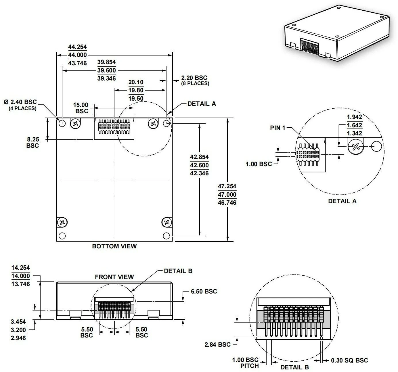
Figure 1 Module Outline Dimension Drawing
Product Marking & Coordinate Definition
During installation, the carrier coordinate system of the module must maintain a fixed relative relationship with the carrier coordinate system of the target equipment. The carrier coordinate system definition of MSU204A MEMS inertial measurement module is shown below.
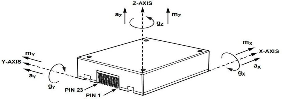
Figure 2 Inertial Sensor Axis Reference Diagram
Interface Characteristics
The MSU204A inertial measurement module uses a customized double-row pin connector FTMH-112-02-H-DH for external signal output (mating plug: Samtec CLM-112-02 or equivalent alternative), which supplies power and realizes external communication. The pin assignment of the connector is defined in Table 2.
Table 2 Connector Pin Definition of MSU204A Inertial Measurement Module
|
Pin Numbers |
Name |
Type |
Description |
|
10, 11, 12 |
VDD |
Power Supply |
- |
|
13, 14, 15 |
GND |
Power Ground |
- |
|
7 |
DIO1 |
Input / Output |
Configurable general-purpose IO |
|
9 |
DIO2 |
Input / Output |
|
|
1 |
DIO3 |
Input / Output |
|
|
2 |
DIO4 |
Input / Output |
|
|
3 |
SPI-CLK |
Input |
SPI master-slave mode fixed, non-configurable |
|
4 |
SPI-MISO |
Output |
|
|
5 |
SPI-MOSI |
Input |
|
|
6 |
SPI-CS |
Input |
|
|
16 |
UART-0-TXD |
Output |
UART0, debug-only |
|
17 |
UART-0-RXD |
Input |
|
|
8 |
RST |
Input |
Hardware reset |
|
23 |
VDD RTC |
Power Supply |
Unused |
|
22, 24, 18, 19, 20, 21 |
NC |
Reserved |
No internal connection |
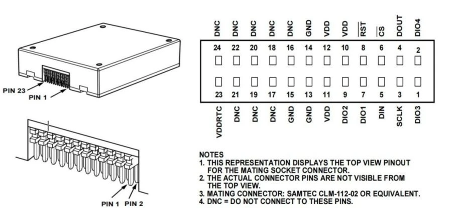
Figure 3 External Connector Pin Label Diagram
When the supply voltage drops below the device operating threshold, the power-off hold time tOFF before re-powering shall not be less than 3 seconds. Insufficient power-off interval may cause abnormal startup, latch-up or initialization failure of the device.
External Communication
The MSU204A is a self-contained sensor system. It automatically starts up after valid power supply, completes initialization, then starts sampling, processing and writing calibrated sensor data to output registers, which can be accessed via SPI interface. The SPI bus is usually connected to a compatible port of an embedded processor. Four SPI signals support synchronous serial data transmission. Under factory default configuration, DIO4 serves as data ready flag; this pin will pull high when new valid data exists in output registers.
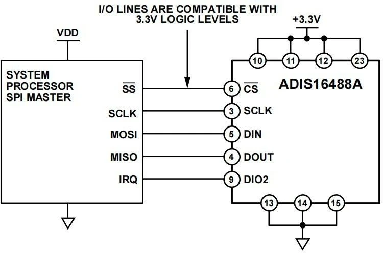
Figure 4 Electrical Connection Schematic
Table 3 General SPI Host Configuration
|
Host Parameter |
Description |
|
Host Mode |
MSU204A operates as SPI slave device |
|
SCLK Frequency |
Max serial clock ≤ 10 MHz |
|
SPI Mode |
Mode 3 (CPOL=1, CPHA=1) |
|
Bit Order |
MSB-first transmission |
|
Data Width |
16-bit shift register frame |
The SPI interface supports full-duplex communication: the external processor can write DIN data while reading DOUT data if the previous transaction is a read request (see Figure 4). Figure 4 provides bit encoding examples for DIN and DOUT signals.

Figure 5 SPI Communication Bit Sequence
The MSU204A automatically activates Page 0 for data register access after power-up. After accessing other register pages, write 0x00 to the PAGE_ID register (DIN=0x8000) to switch back to Page 0.
Reading a single register requires two 16-bit SPI cycles:
The first cycle sends register address request with bit allocation defined in Figure 3
The second cycle returns target register data via DOUT
The first bit of DIN command is 0, followed by high/low bytes of register address. The last 8 bits are dummy bits, but a complete 16 SCLK cycle is required for SPI reception of the request.
Figure 5 illustrates two consecutive register read operations: DIN=0x1A00 requests Z_GYRO_OUT register data, then DIN=0x1800 requests Z_GYRO_LOW register data.

Figure 6 SPI Read Transaction Example
Table 4 User Register Memory Map (N/A = Not Applicable)
|
R/W |
Page ID |
Address |
Default Value |
Register Description |
|
R/W |
0x00 |
0x00 |
0x00 |
Page ID Select Register |
|
R |
0x00 |
0x0E |
N/A |
Temperature Output |
|
R |
0x00 |
0x10 |
N/A |
X-axis Gyro Output (Low Word) |
|
R |
0x00 |
0x12 |
N/A |
X-axis Gyro Output (High Word) |
|
R |
0x00 |
0x14 |
N/A |
Y-axis Gyro Output (Low Word) |
|
R |
0x00 |
0x16 |
N/A |
Y-axis Gyro Output (High Word) |
|
R |
0x00 |
0x18 |
N/A |
Z-axis Gyro Output (Low Word) |
|
R |
0x00 |
0x1A |
N/A |
Z-axis Gyro Output (High Word) |
|
R |
0x00 |
0x1C |
N/A |
X-axis Accelerometer Output (Low Word) |
|
R |
0x00 |
0x1E |
N/A |
X-axis Accelerometer Output (High Word) |
|
R |
0x00 |
0x20 |
N/A |
Y-axis Accelerometer Output (Low Word) |
|
R |
0x00 |
0x22 |
N/A |
Y-axis Accelerometer Output (High Word) |
|
R |
0x00 |
0x24 |
N/A |
Z-axis Accelerometer Output (Low Word) |
|
R |
0x00 |
0x26 |
N/A |
Z-axis Accelerometer Output (High Word) |
|
R |
0x00 |
0x28 |
N/A |
X-axis Magnetometer Output (High Word) |
|
R |
0x00 |
0x2A |
N/A |
Y-axis Magnetometer Output (High Word) |
|
R |
0x00 |
0x2C |
N/A |
Z-axis Magnetometer Output (High Word) |
|
R |
0x00 |
0x2E |
N/A |
Barometric Pressure Output (Low Word) |
|
R |
0x00 |
0x30 |
N/A |
Barometric Pressure Output (High Word) |
|
R |
0x00 |
0x7E |
0x4068 |
Part ID Output (Compatible with ADIS16488) |
Inertial Sensor Data Format
The output registers of gyroscope, accelerometer and barometer adopt 32-bit binary format, split into two separate 16-bit registers. Figure 7 shows how register pairs compose inertial measurement data. For example, X_GYRO_OUT stores high 16 bits, X_GYRO_LOW stores low 16 bits. In most scenarios, only high 16-bit register data is sufficient to meet resolution requirements.
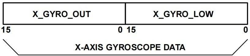
Figure 7 Gyroscope Output Format Example (DEC_RATE > 0)
Temperature Calculation Formulas
Current Temperature = 25 + TEMP_OUT × 0.00565
Gyroscope Calculation Formula
|
X-axis Gyroscope |
X_GYRO_OUT |
X_GYRO_LOW |
|
1LSB = 0.02 °/s |
The weight of the most significant bit (MSB) is 0.01 °/s, and the weight of subsequent bits decreases by half sequentially. |
|
|
0. 02 * X_GYRO_OUT |
0.01*MSB+0.005*... |
Accelerometer Calculation Formula
|
X-axis Accelerometer |
X_ACCL_OUT |
X_ACCL_LOW |
|
1LSB = 0.8mg |
The weight of the most significant bit (MSB) is 0.4 mg, and the weight of subsequent bits decreases by half sequentially. |
|
|
0.8 * X_ACCL_OUT |
0.4 * MSB + 0.2*... |
Magnetic Field Calculation Formula:
|
X-axis Magnetometer |
X_MAGN_OUT |
|
|
1LSB = 0.1mGauss |
||
|
0.1 * X_MAGN_OUT |
Barometric Pressure Calculation Formula
|
Barometric Pressure (Bar) |
BAROM_OUT |
BAROM_LOW |
|
1LSB = 40ubar |
The weight of the most significant bit (MSB) is 20 μbar, and the weight of subsequent bits decreases by half sequentially. |
|
|
40 * BAROM_OUT |
20 * MSB + 10*.... |
Product Operation Precautions
- Confirm the electrical pin definition strictly; follow the pinout arrangement during wiring to avoid misconnection.
- This product is precision measuring equipment. Avoid impact, collision or mechanical overload exceeding the rated limit during handling.
- Mounting flatness significantly affects angular rate measurement. Ensure the mounting surface has high flatness to eliminate installation-induced error.
- Fix the module firmly and reliably to prevent measurement drift caused by loose assembly.
- Take anti-static protection measures during installation and operation; wearing an anti-static wristband is recommended.
- Operate the device strictly in accordance with this manual and verify the external environment meets operating requirements. Do not disassemble the housing or modify internal hardware if any fault occurs; contact our technical support team for troubleshooting.
Hot Tags: msu204a mems inertial measurement unit, China msu204a mems inertial measurement unit manufacturers, factory