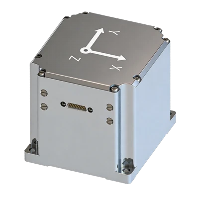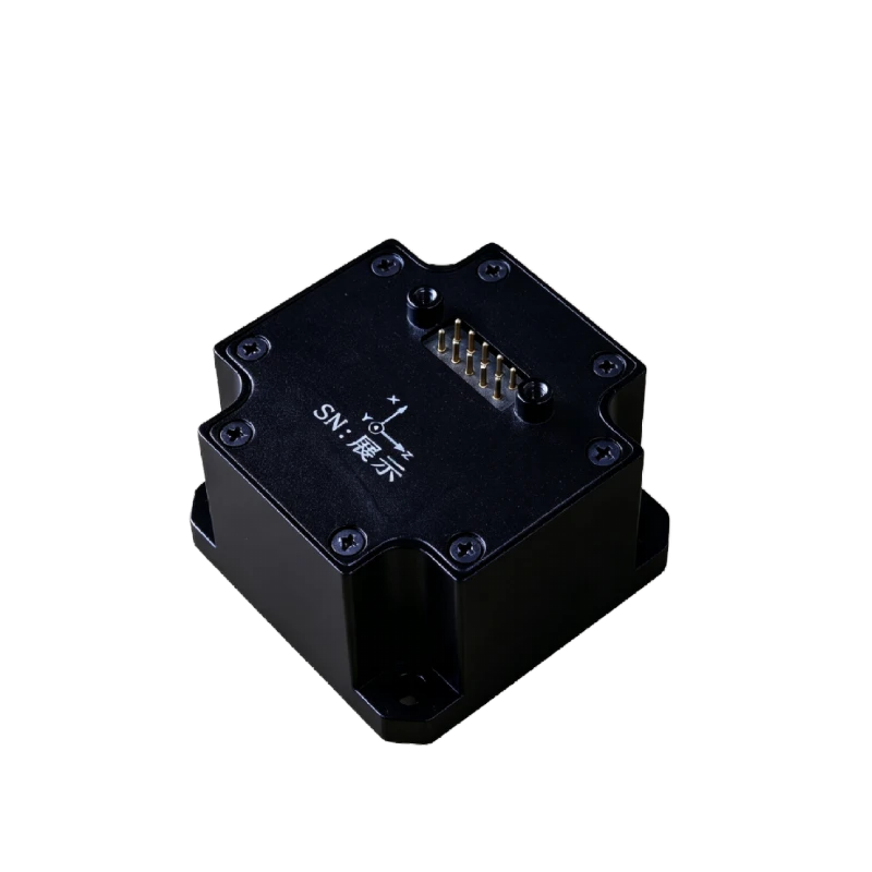
MSN302 High Precision MEMS North Finder
100% Domestic devices
Strong resistance to harsh mechanical environments
Software online upgrade
Description
Key Features
- High performance, compact size
- -40°C to +85°C full-temp. calibration compensation
- 100% Domestic devices
- Strong resistance to harsh mechanical environments
- Software online upgrade
- Zero-velocity heading hold
- Configurable north-finding time
- Installation error angle correction function
Applications
- Orientation in complex environments such as mines
- Man-portable north finding
- Oil well inclinometer north finding
- Pipeline measurement
- Underwater navigation
Product Introduction
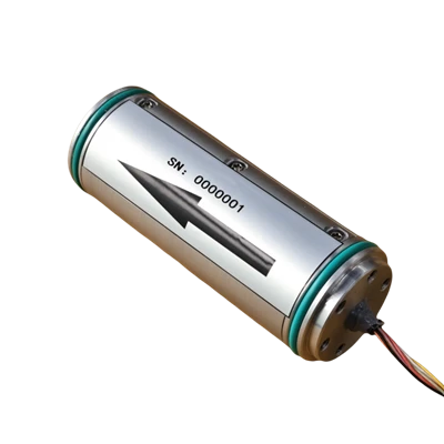
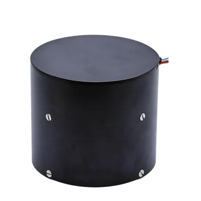
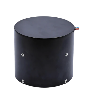
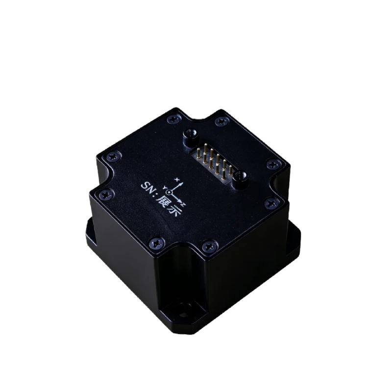
MSN302 MEMS North Finder is a highly reliable and cost-effective six-axis MEMS inertial sensor. The North Finder integrates high-performance MEMS gyroscopes and MEMS accelerometers, enabling autonomous north finding and level attitude measurement under both static and dynamic base conditions, while maintaining long-term attitude accuracy. It can be widely applied for autonomous north finding and attitude measurement in confined spaces (underwater, downhole).
MSN302 High-Precision MEMS North Finder
|
MEMS Gyroscope |
|
|
Range (°/s) |
±200 |
|
Bias @ Full temp. (°/h, 3σ) |
≤0.3 |
|
Bias Stability (°/h, 10s smoothing) |
≤0.1 |
|
Bias Instability (°/h, Allan, typ) |
≤0.02 |
|
Bias Repeatability (°/h) |
≤0.1 |
|
Angular Random Walk (°/√h) |
≤0.01 |
|
Scale Factor Nonlinearity (ppm) |
≤100 |
|
Cross-Coupling (rad) |
≤0.001 |
|
Bandwidth (Hz) |
≥50 |
|
MEMS Accelerometer |
|
|
Range (g) |
±10 |
|
Bias @ Full temp. (mg, 3σ) |
≤1 |
|
Bias Stability (ug, 10s smoothing) |
≤20 |
|
Bias Instability (ug, Allan, typ) |
≤10 |
|
Bias Repeatability (ug) |
≤20 |
|
Velocity Random Walk (m/s/√h) |
≤0.02 |
|
Scale Factor Nonlinearity (ppm, ±1g) |
≤100 |
|
Cross-Coupling (rad) |
≤0.001 |
|
Bandwidth (Hz) |
≥50 |
|
Navigation accuracy |
|
|
North Finding Accuracy (°, 1σ) |
≤0.5secL (L for latitude) |
|
Attitude Accuracy (°, 1σ) |
≤0.05 |
|
Physical Characteristics |
|
|
Power Supply (V) |
5~12 (Ripple ≤ 100mV) |
|
Steady-state Power (W) |
≤2 |
|
Startup Time (s) |
≤2 |
|
Update Rate (Hz, max) |
200 |
|
Dimensions (mm×mm×mm) |
47×47×35.5 |
|
Weight (g) |
100±10g |
|
Operating Environment |
|
|
Operating Temp. (°C) |
-40~+85 |
|
Storage Temp. (°C) |
-55~+85 |
|
Vibration (g, RMS) |
6.06,20~2000Hz |
|
Shock (g) |
500g/1ms |
Product Introduction
Product Overview
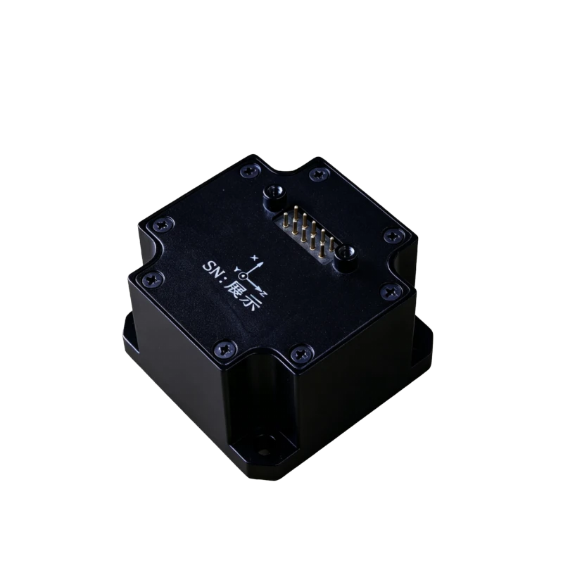
The MSN302 MEMS North Finder is a highly reliable, cost-effective six-axis MEMS inertial sensor,The North Finder integrates a high-performance MEMS gyroscope and MEMS accelerometer in a standalone structure, It supports auto north finding and horizontal attitude measurement under both static and swinging base conditions, maintaining long-term attitude accuracy. It is widely applicable for autonomous north finding and attitude measurement in confined spaces (underwater, downhole).
Key Features
- High performance, compact size
- -40°C to +85°C calibration and compensation over full temperature range
- 100% domestically produced components
- Harsh mechanical environment resistance
- Online firmware update capability
- Zero-Velocity Heading Hold
- North Finding Time Configurable
- Installation misalignment angle correction function
Applications
- Orientation in complex environments such as mines
- Soldier-Borne North Finding
- Petroleum Inclination and North Finding
- Pipeline Surveying
- Underwater Navigation
Table 1 MSN302 North Finder Performance Specifications
|
Gyroscope |
|
|
Range (°/s) |
±200 |
|
Bias @Full temp.(°/h,3σ) |
≤0.3 |
|
Bias Stability (°/h,10ssmoothing) |
≤0.1 |
|
Bias Instability (°/h,allan,typ) |
≤0.02 |
|
Bias Repeatability (°/h) |
≤0.1 |
|
Angle Random Walk (°/√h) |
≤0.01 |
|
Scale Factor Nonlinearity (ppm) |
≤100 |
|
Cross-Axis Coupling (rad) |
≤0.001 |
|
Bandwidth (Hz) |
≥50 |
|
Accelerometer |
|
|
Range (g) |
±10 |
|
Bias @Full temp. (mg, 3σ) |
≤1 |
|
Bias Stability (ug, 10s smoothing) |
≤20 |
|
Bias Instability (ug, Allan, typ) |
≤10 |
|
Bias Repeatability (ug) |
≤20 |
|
Velocity Random Walk (m/s/√h) |
≤0.02 |
|
Scale Factor Nonlinearity (ppm, ±1g) |
≤100 |
|
Cross-Axis Coupling (rad) |
≤0.001 |
|
Bandwidth (Hz) |
≥50 |
|
Navigation Accuracy |
|
|
Auto north finding accuracy (°, 1σ) |
≤0.5secL(L represents the local latitude) |
|
Attitude accuracy (°, 1σ) |
≤0.05 |
|
Physical Characteristics |
|
|
Power Supply (V) |
5~12(Ripple ≤100mV) |
|
Steady-State Power (W) |
≤2 |
|
Startup Time (s) |
≤2 |
|
Update rate (Hz, max) |
200 |
|
Dimensions (mm×mm×mm) |
47×47×35.5 |
|
Weight (g) |
100±10g |
|
Operating Environment |
|
|
Operating Temperature (°C) |
-40~+85 |
|
Storage Temperature (°C) |
-55~+85 |
|
Vibration (g, RMS) |
20~2000HZ,6.06 |
|
Shock (g) |
500g/1ms |
Mechanical Characteristics
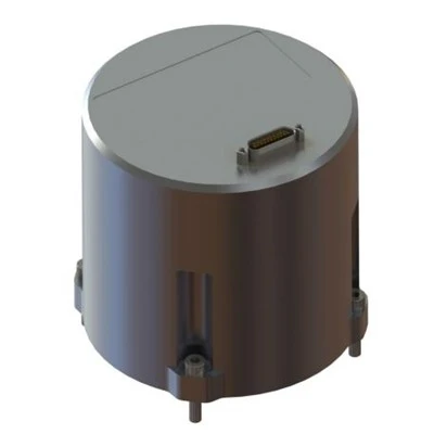
The MSN302 North Finder system uses an aluminum alloy structure, which is lightweight with high structural integrity, resistant to vibration and shock. The unit dimensions are 47×47×35.5mm, as shown in Figure 1, and the unit is fixed with 4*M4 screws.
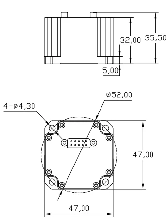
Figure 1 Mechanical Dimensions
Product Marking and Orientation
The coordinate system definition of the High-Precision MEMS North Finder is shown in the figure. The product is placed horizontally with the marking arrow pointing upward. In the body frame: the X-axis points to the front of the vehicle, the Y-axis points upward, and the Z-axis points to the right, forming a "Front-Up-Right" coordinate system, corresponding to the "North-Up-East" navigation frame.
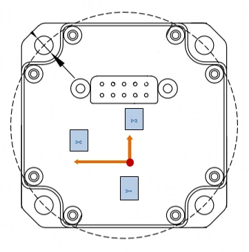
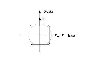
Figure 2 North Finder Body Frame and Navigation Frame Axis Definitions.
Heading Angle: The angle between the projection of the vehicle's longitudinal axis (X-axis in the figure) on the local horizontal plane and the local geographic north direction. Positive toward north-to-east. Range: 0° to 360°, as shown in the figure below:
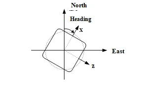
Figure3 Heading Angle Measurement Definition (Top View)
Pitch Angle: The angle between the vehicle's longitudinal axis (X-axis in the figure) and its horizontal projection line. Positive when the vehicle nose pitches up. Range: -90° to 90°, as shown in the figure below:
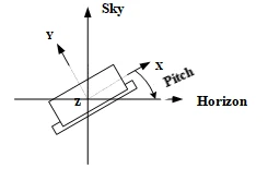
Figure4 Pitch Angle Measurement Definition (Left View)
Roll Angle: The angle between the vehicle's lateral axis (Z-axis in the figure) and the horizon. Positive when the vehicle tilts to the right. Range: -180° to 180°, as shown in the figure below:
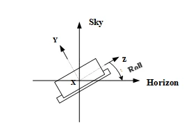
Figure5 Roll Angle Measurement Definition (Front View)
Virtual Heading Angle: When the product operates in an inverted position (pitch angle of -90°), the roll angle and heading angle become singular angles and cannot accurately represent the vehicle's attitude. Therefore, a virtual heading angle is defined as the angle measured clockwise from the true north direction to the Y-axis, with a range of 0 to 360°, as shown in the figure below.
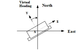
Figure6 Virtual Heading Angle (Top View)
During operation, when the pitch angle is near 90°, the roll angle and heading angle have singularity issues. In general engineering applications, two different angle combinations are used alternately based on the pitch angle output. The switching criteria are as follows:
When the vehicle pitch angle is between -85° and +85°, use heading angle, pitch angle, and roll angle.
When the vehicle pitch angle is between -85° to -90° or +85° to +90°, use pitch angle and virtual heading angle.
The quaternion represents the rotation between the North-Up-East navigation frame and the Front-Up-Right body frame. The relationship between the quaternion and the attitude matrix is as follows:
Note: b denotes the Front-Up-Right body frame; n denotes the North-Up-East navigation frame.
Interface Definition
The MSN302 High-Precision MEMS North Finder uses a custom CH-26A-10TJ dual-row pin header connector for external output (mating connector: CH-26A-10ZJ), Pin pitch 2.54mm, mainly providing power supply and communication for the North Finder system. The connector pin definitions are as shown in the table below shown.
Table 2 MSN302 High-Precision MEMS North Finder Connector Pin Definitions
|
CH-26A-10TJ PinNo. |
Definition |
Test Equipment Side |
|
1 |
POWER_IN |
DC 5V~12V power supply |
|
6 |
GND |
|
|
2 |
RS422 Rx+ |
RS422 Tx+ |
|
7 |
RS422 Rx- |
RS422 Tx- |
|
3 |
RS422 Tx+ |
RS422 Rx+ |
|
8 |
RS422 Tx- |
RS422 Rx- |
After the supply voltage drops below the device operating threshold voltage, the power-off hold time before re-powering tOFF must not be less than 3s; insufficient power-off interval may cause abnormal startup, latch-up, or initialization failure.
Communication Protocol
Protocol 1:XDNS-55AAProtocol
The MSN302 High-Precision MEMS North Finder outputs data in periodic broadcast mode by default, with an output frequency of 200 Hz, 96 bytes per frame, baud rate of 460800 bps, 1 start bit, 8 data bits, 1 stop bit, no parity. For multi-byte variables, the low byte is sent first followed by the high byte. The typical communication protocol is shown in Table3shown.
Table 3 MSN302 High-Precision MEMS North Finder Communication Protocol
|
No. |
Byte Start |
Byte Count |
Content |
Equivalent |
Range |
Unit |
Remarks |
|
|
1 |
0 |
1 |
0x55 |
1 |
Frame Header |
|||
|
2 |
1 |
1 |
0xAA |
1 |
Frame Header |
|||
|
3 |
2 |
1 |
92 |
1 |
Data Length |
|||
|
4 |
3 |
4 |
PC num |
1 |
5ms |
5ms count value |
||
|
5 |
7 |
1 |
System Operating Status |
- |
- |
- |
16 (0x10): Self-test in progress; 18 (0x12): Self-test passed: 31 (0x1F): Self-test error: 51 (0x33): Coarse alignment: 53 (0x35): Fine alignment 65 (0x41): Navigating 67 (0x43): Zero velocity correction |
|
|
6 |
8 |
1 |
Reserved |
- |
- |
- |
||
|
7 |
9 |
1 |
Over-Range Status |
- |
- |
- |
After the product enters alignment, within one navigation cycle of 5ms, bit0: X gyroscope over-range set to 1; bit1: Y gyroscope over-range set to 1; bit2: Z gyroscope over-range set to 1; Bit3: X accelerometer over-range set to 1; Bit4: Y accelerometer over-range set to 1; Bit5: Z accelerometer over-range set to 1; After re-alignment, the above status is cleared to 0. |
|
|
8 |
10 |
1 |
Command Response Status |
0x10: Successfully responded to correct command, sending 5 packets continuously. 0x1F: Command error, sending 5 packets continuously, prompting user to check command configuration (output data or command out of range), original process unchanged. Note: Upon receiving a valid command, 5 packets with 0x10 status are sent as feedback, followed by a soft reset. Upon receiving an invalid command, 5 packets with 0x1F status are sent as feedback, and the original state is maintained. |
||||
|
9 |
11 |
2 |
Total North Finding Time |
1 |
- |
s |
||
|
10 |
13 |
2 |
Remaining North Finding Time |
1 |
s |
|||
|
11 |
15 |
4 |
Angular Rate X |
0.0000005 |
°/s |
Average within output cycle (forward) |
||
|
12 |
19 |
4 |
Angular Rate Y |
0.0000005 |
°/s |
Average within output cycle (upward) |
||
|
13 |
23 |
4 |
Angular Rate Z |
0.0000005 |
°/s |
Average within output cycle (rightward) |
||
|
14 |
27 |
4 |
Acceleration X |
0.000001 |
m/s2 |
Average within output cycle (forward) |
||
|
15 |
31 |
4 |
Acceleration Y |
0.000001 |
m/s2 |
Average within output cycle (upward) |
||
|
16 |
35 |
4 |
Acceleration Z |
0.000001 |
m/s2 |
Average within output cycle (rightward) |
||
|
17 |
39 |
4 |
Integrated Longitude |
0.0000001 |
° |
Instantaneous value at output time |
||
|
18 |
43 |
4 |
Integrated Latitude |
0.0000001 |
° |
Instantaneous value at output time |
||
|
19 |
47 |
2 |
Integrated Altitude |
0.5 |
m |
Instantaneous value at output time |
||
|
20 |
49 |
2 |
Integrated North Velocity |
0.04 |
m/s |
Instantaneous value at output time |
||
|
21 |
51 |
2 |
Integrated Up Velocity |
0.04 |
m/s |
Instantaneous value at output time |
||
|
22 |
53 |
2 |
Integrated East Velocity |
0.04 |
m/s |
Instantaneous value at output time |
||
|
23 |
55 |
2 |
Roll Angle |
0.006 |
[-180~180] |
° |
Instantaneous value at output timeint16 |
|
|
24 |
57 |
2 |
Heading Angle |
0.006 |
[0,360] |
° |
Positive toward north-to-east Instantaneous value at output timeUint16 |
|
|
25 |
59 |
2 |
Pitch Angle |
0.006 |
[-90,90] |
° |
Instantaneous value at output timeint16 |
|
|
26 |
61 |
1 |
Gyroscope Temperature |
1 |
℃ |
Instantaneous value at output time |
||
|
27 |
62 |
1 |
Accelerometer Temperature |
1 |
℃ |
Instantaneous value at output time |
||
|
28 |
63 |
4 |
Quaternion q0 |
Based on North-Up-East coordinate system. IEEE 32-bit floating point, little-endian. |
||||
|
29 |
67 |
4 |
Quaternion q1 |
Same as above |
||||
|
30 |
71 |
4 |
Quaternion q2 |
- |
- |
Same as above |
||
|
31 |
75 |
4 |
Quaternion q3 |
- |
Same as above |
|||
|
32 |
79 |
6 |
IMU over-range counter |
1 |
1 |
If an over-range occurs once per 5ms navigation cycle, increment by 1. After accumulating to 255, restart counting. If re-alignment occurs, restart counting. Little-endian format, in the order of GxGyGzAxAyAz, each axis is Uint8. |
||
|
33 |
85 |
1 |
Reserved |
1 |
UInt8 |
|||
|
34 |
86 |
1 |
Reserved |
1 |
UInt8 |
|||
|
35 |
87 |
2 |
Reserved |
UInt8 |
||||
|
36 |
89 |
2 |
Virtual Heading Angle |
0.006 |
[0,360]deg |
|||
|
37 |
91 |
2 |
Reserved |
Little-Endian Format |
||||
|
38 |
93 |
1 |
Vertical Mode Flag |
1 |
UInt8, 0: Horizontal mode; 1: Vertical launch mode; |
|||
|
39 |
94 |
1 |
Output Protocol Format |
1 |
0x00: General north finder protocol 0xFF: General petroleum north finding protocol |
|||
|
40 |
95 |
1 |
Checksum |
1 |
Low 8 bits of the cumulative sum of bytes at indices 2 to 94 |
|||
Protocol 2:Host Computer to North Finder Command Protocol
The MSN302 High-Precision MEMS North Finder can respond to commands in real time. The host computer sends trigger commands to the North Finder system according to the following protocol: baud rate 460800 bps, 1 start bit, 8 data bits, 1 stop bit, no parity. For multi-byte variables, the low byte is sent first followed by the high byte. The communication protocol is shown in the table below (the North Finder can respond to control commands after passing self-test.
Table 4 MSN302 High-Precision MEMS North Finder Host Computer Control Command Protocol
|
First Byte |
Byte Count |
Signal Name |
Dimension, Unit, or Content |
Equivalent |
Interface Accuracy Description |
|
1 |
1 |
Frame Header 1 |
Content: 55H |
1 |
8-bit unsigned integer |
|
2 |
1 |
Frame Header 2 |
Content: AAH |
1 |
8-bit unsigned integer |
|
3 |
1 |
Data Length |
Content: 24H |
1 |
8-bit unsigned integer |
|
4 |
4 |
Loaded Longitude |
[-180,180]deg |
0.0000001 |
Little-Endian Format |
|
5 |
4 |
Loaded Latitude |
[-90,90]deg |
0.0000001 |
Little-Endian Format |
|
6 |
4 |
Loaded Altitude |
m |
1 |
IEEE 32-bit floating point Little-Endian Format |
|
7 |
4 |
Reserved 1 |
NA |
1 |
- |
|
8 |
2 |
Data Validity Mode |
NA |
1 |
bit0: 1 = LLA information valid; bit1: 1 = loaded heading information valid; bit2: 1 = alignment time valid bit3: 1 = baud rate and period valid bit4: 1 = installation misalignment angle valid All bits being 0 means all invalid. |
|
9 |
2 |
Reserved 2 |
NA |
|
|
|
10 |
2 |
Reserved 3 |
NA |
||
|
11 |
1 |
Output Baud Rate Configuration |
NA |
1 |
0:9600bps; 1:38400; 2:115200; 3:230400; 4:460800; 5:921600; |
|
12 |
1 |
Output Period |
NA |
1 |
0:5ms 1:10ms 2:20ms; 3:50ms; 4:100ms; 5:200ms; 6:500ms: 7:1s; 8:2s; 9:5s; |
|
13 |
2 |
2 |
Roll Installation Misalignment Angle Between INS and Target Point UsrTransRoll |
0.006 |
[-180~180] |
|
14 |
2 |
2 |
Yaw Installation Misalignment Angle Between INS and Target Point UsrTransYaw |
0.006 |
[-180~180] |
|
15 |
2 |
2 |
Pitch Installation Misalignment Angle Between INS and Target PointUsrTransPitch |
0.006 |
[-180~180] |
|
16 |
2 |
Reserved 4 |
NA |
|
|
|
17 |
2 |
User Command |
NA |
1 |
16-bit unsigned integer; 1) 0x0011: Static auto north finding command; 3) 0x0077: Write alignment time to flash command; 4) 0x0099: Write baud rate and output frequency to flash command 5)0x00AA:Write attitude installation misalignment angle to flash command Other invalid values: command not responded; |
|
18 |
2 |
Alignment Time |
[120,6553.5] |
0.1 |
16-bit unsigned integer; (1) Under the static auto north finding command, the alignment time value is coarse alignment time (30s) + fine alignment time, which should not be less than 120s. |
|
19 |
1 |
Checksum |
Low 8 bits of the cumulative sum of all bytes from Data Length (inclusive) to the byte before Checksum |
1 |
Low 8 bits of the cumulative sum of bytes at indices 2 to 38 |
Precautions
- Pay attention to the product electrical interface definition. Strictly follow the pin layout during use to avoid incorrect connections;
- As a precision measurement device, avoid subjecting the product to shocks, collisions, or other conditions beyond its tolerance during handling;
- Before powering on, verify the power supply. Do not use a computer USB port directly as it may cause damage due to insufficient power. If repeatability verification is needed, the power-on interval must not be less than 10s;
- Product installation significantly affects angular rate measurement. To avoid introducing installation errors, the mounting surface must have good flatness;
- To ensure measurement accuracy, the product must be mounted securely and firmly to avoid introducing measurement errors due to loosening;
- During installation and operation, observe ESD protection; an ESD wrist strap is recommended;
- Strictly follow the requirements in this manual and confirm that the external environment matches the operating requirements. If any issue occurs, do not open the cover or modify the internal structure. Contact our technical support team promptly.
Hot Tags: msn302 high precision mems north finder, China msn302 high precision mems north finder manufacturers, factory