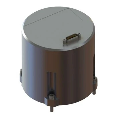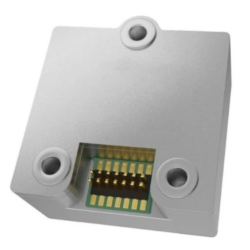
MSU206 MEMS Inertial Measurement Unit
Compatible with UART / SPI serial communication interfaces
Built-in temperature sensor
Pin-to-pin compatible with ADIS16575
Description
Main Features
 3-axis digital gyroscope, measurement range ±400 °/s
 3-axis digital accelerometer, measurement range ±40 g
 Compatible with UART / SPI serial communication interfaces
 Built-in temperature sensor
 Pin-to-pin compatible with ADIS16575
Application Fields
 Navigation, guidance and control systems
 Attitude control
 Automatic control systems
Robot control
 Gimbal stabilization and control
 Vehicle positioning and orientation systems
Product Overview
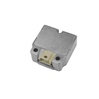
The MSU206 MEMS Inertial Measurement Unit (IMU) is a high-reliability, cost-effective 6-axis inertial measurement module. It is widely applied to navigation, control and dynamic measurement systems for vehicles, vessels, UAVs and other carriers. The gyroscope and accelerometer integrated in MSU206 series adopt cutting-edge MEMS inertial manufacturing technology, delivering outstanding vibration resistance and temperature performance. Full-temperature error compensation is implemented for zero bias, scale factor and non-orthogonality error, enabling sustained high measurement precision over long-term operation.
Unique Technology
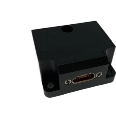
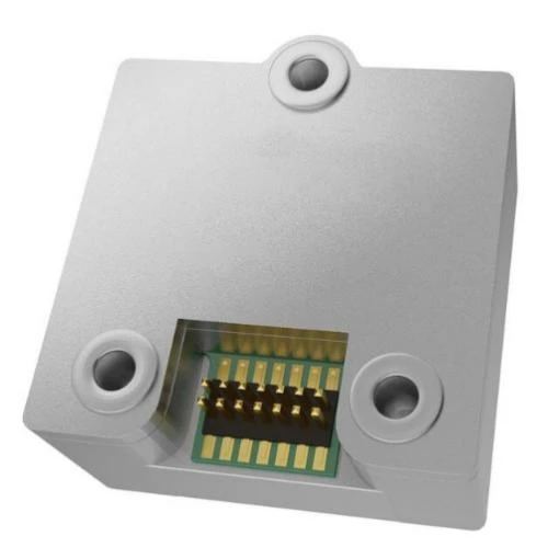
Company is a high-tech enterprise with full closed-loop capabilities from fiber winding to FOGs, fiber/MEMS inertial products, IMU circuits, software, and test equipment. End-to-end process control improves quality and reduces costs. Operating under ISO9001, it ensures reliability and consistency. The MSU206 inertial measurement module adopts an aluminum alloy housing, which features light weight, high structural strength, and excellent resistance to vibration and shock.
MSU206 MEMS Inertial Measurement Unit
MSU206 MEMS Inertial Measurement Unit Performance Parameters
|
Parameter |
Technical Index |
|
Gyroscope |
|
|
Measurement Range (°/s) |
±500 |
|
Full-Temperature Bias (°/h, 3σ) |
≤60 |
|
Bias Stability (°/h, 10s averaging window) |
≤5 |
|
Bias Instability (°/h, Allan variance, typical) |
≤0.5 |
|
Bias Repeatability (°/h) |
≤5 |
|
Angular Random Walk (°/√h) |
≤0.2 |
|
Scale Factor Nonlinearity (ppm) |
≤100 |
|
Bandwidth (Hz) |
≥200Hz |
|
Cross-Coupling Error (rad) |
≤0.001 |
|
Bias Variation Under Vibration (°/h, 20~2000 Hz, 6.06 g) |
≤10 |
|
Accelerometer |
|
|
Measurement Range (g) |
±40 |
|
Full-Temperature Bias (mg, 3σ) |
≤3(XY)≤5(Z) |
|
Bias Stability (μg, 10s averaging window) |
≤100 |
|
Bias Instability (μg, Allan variance, typical) |
≤30 |
|
Bias Repeatability (μg) |
≤100 |
|
Velocity Random Walk (m/s/√h) |
≤0.03 |
|
Scale Factor Nonlinearity (ppm, ±1g input) |
≤200 |
|
Cross-Coupling Error (rad) |
≤0.001 |
|
Bandwidth (Hz) |
≥200Hz |
|
Magnetometer |
|
|
Measurement Range (Gs) |
±8 |
|
Resolution (μGs) |
≤200 |
|
Noise Density (μGs/√Hz) |
≤50 |
|
Bandwidth (Hz) |
≥200 |
|
Physical Characteristics |
|
|
Supply Voltage (V) |
3.3±0.3(Ripple≤100mV) |
|
Maximum Data Update Rate (Hz) |
One SPI channel and one UART channel |
|
Weight (g) |
22.4×22.3×13.7 |
|
Supply Voltage (V) |
12±2 |
|
Operating Environment |
|
|
Operating Temperature (℃) |
-40~80 |
|
Storage Temperature (℃) |
-55~85 |
|
Vibration (g, RMS, 20~2000 Hz) |
20~2000HZ,6.06 |
|
Shock (g, 1 ms half-sine pulse) |
1000/1ms |
Product Overview
The MSU206 MEMS Inertial Measurement Unit (IMU) is a high-reliability, cost-effective 6-axis inertial measurement module. It is widely applied to navigation, control and dynamic measurement systems for vehicles, vessels, UAVs and other carriers. The gyroscope and accelerometer integrated in MSU206 series adopt cutting-edge MEMS inertial manufacturing technology, delivering outstanding vibration resistance and temperature performance. Full-temperature error compensation is implemented for zero bias, scale factor and non-orthogonality error, enabling sustained high measurement precision over long-term operation.
Key Features
- Core sensors domestically manufactured
- 3-axis digital gyroscope, measurement range ±400 °/s
- 3-axis digital accelerometer, measurement range ±40 g
- Full-temperature calibration and compensation from -40 ℃ to +80 ℃ (for gyroscopes and accelerometers)
- Compatible with UART / SPI serial communication interfaces
- Built-in temperature sensor
- Compact dimension and lightweight design
- Pin-to-pin compatible with ADIS16575
Application Fields
- Navigation, guidance and control systems
- Attitude control
- Automatic control systems
- Robot control
- Gimbal stabilization and control
- Precision instruments and meters
- Attitude reference for UAVs, ground vehicles, ships and boats
- Mobile mapping data acquisition
- Vehicle positioning and orientation systems
Technical Specifications
Table 1 Performance Parameters of MSU206 Inertial Measurement Module
|
Parameter |
Technical Index |
|
Gyroscope |
|
|
Measurement Range (°/s) |
±500 |
|
Full-Temperature Bias (°/h, 3σ) |
≤60 |
|
Bias Stability (°/h, 10s averaging window) |
≤5 |
|
Bias Instability (°/h, Allan variance, typical) |
≤0.5 |
|
Bias Repeatability (°/h) |
≤5 |
|
Angular Random Walk (°/√h) |
≤0.2 |
|
Scale Factor Nonlinearity (ppm) |
≤100 |
|
Bandwidth (Hz) |
≥200Hz |
|
Cross-Coupling Error (rad) |
≤0.001 |
|
Bias Variation Under Vibration (°/h, 20~2000 Hz, 6.06 g) |
≤10 |
|
Accelerometer |
|
|
Measurement Range (g) |
±40 |
|
Full-Temperature Bias (mg, 3σ) |
≤3(XY)≤5(Z) |
|
Bias Stability (μg, 10s averaging window) |
≤100 |
|
Bias Instability (μg, Allan variance, typical) |
≤30 |
|
Bias Repeatability (μg) |
≤100 |
|
Velocity Random Walk (m/s/√h) |
≤0.03 |
|
Scale Factor Nonlinearity (ppm, ±1g input) |
≤200 |
|
Cross-Coupling Error (rad) |
≤0.001 |
|
Bandwidth (Hz) |
≥200Hz |
|
Magnetometer |
|
|
Measurement Range (Gs) |
±8 |
|
Resolution (μGs) |
≤200 |
|
Noise Density (μGs/√Hz) |
≤50 |
|
Bandwidth (Hz) |
≥200 |
|
Physical Characteristics |
|
|
Supply Voltage (V) |
3.3±0.3(Ripple≤100mV) |
|
Steady-State Power Consumption (W) |
≤1 |
|
Startup Time (s) |
≤2 |
|
Maximum Data Update Rate (Hz) |
One SPI channel and one UART channel |
|
Overall Dimension (mm×mm×mm) |
2000 |
|
Weight (g) |
22.4×22.3×13.7 |
|
Supply Voltage (V) |
12±2 |
|
Operating Environment |
|
|
Operating Temperature (℃) |
-40~80 |
|
Storage Temperature (℃) |
-55~85 |
|
Vibration (g, RMS, 20~2000 Hz) |
20~2000HZ,6.06 |
|
Shock (g, 1 ms half-sine pulse) |
1000/1ms |
Technical Specifications
Mechanical Characteristics
The MSU206 inertial measurement module adopts an aluminum alloy housing, which features light weight, high structural strength, and excellent resistance to vibration and shock. The outline dimension of the module is shown in Figure 1, and the unit is fastened with three M4 screws.
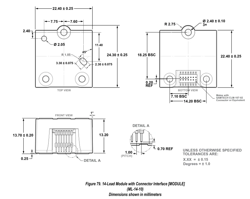
Figure 1 Outline Dimension Drawing
Product Marking & Axis Polarity
During installation, the carrier coordinate system of the module must maintain a fixed relative positional relationship with the carrier coordinate system of the target equipment. The carrier coordinate system definition of the MSU206 MEMS inertial measurement module is provided as follows.
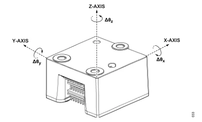
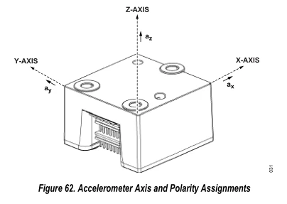
Figure 2 Product Coordinate System
Interface Definition
The MSU206 miniature inertial measurement assembly uses a double-row pin header with 1.0 mm pitch for external signal output, model: 2×7 double-row pin header (1.0 mm pitch). It serves power supply and external communication functions for the module.
The pin assignment definition of the connector is listed in Table 2.
Table 2 Connector Pin Definition of MSU206 Inertial Measurement Module
|
Pin No. |
Name |
Type |
Description |
|
1 |
DR |
Output |
Data Ready Indicator |
|
2 |
SYNC |
Input / Output |
External Synchronization Input & Output |
|
3 |
SPI1_SCK |
Input / Output |
SPI Serial Clock |
|
4 |
SPI1_MISO |
Output |
SPI Data Output. The DOUT pin clocks out output data on the falling edge of SCLK |
|
5 |
SPI1_MISI |
Input |
SPI Data Input. The DIN pin clocks in input data on the rising edge of SCLK |
|
6 |
SPI_SS0 |
Input |
SPI Chip Select |
|
7 |
UART_RX |
Input |
UART Receive Port |
|
8 |
NRST |
Input |
Hardware Reset |
|
9 |
WM |
Output |
Watermark Interrupt Signal, used to monitor the fill level of the FIFO queue |
|
10 |
UART_TX |
Output |
UART Transmit Signal |
|
11 |
VDD |
Positive Power Rail |
Positive Power Supply |
|
12 |
SWCLK |
Input |
SWD Clock Signal |
|
13 |
GND |
Negative Power Rail |
Power Ground |
|
14 |
SWD |
Input / Output |
Bidirectional SWD Data Signal |
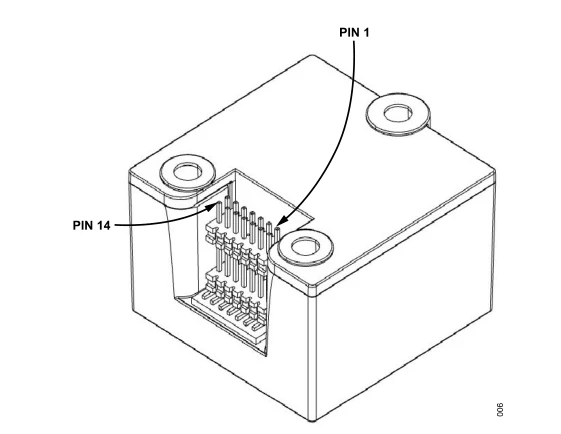
Figure 3 Connector Pinout Diagram
After the supply voltage drops below the device operating threshold, the power-off hold time tOFF before re-powering shall not be less than 3 seconds. Insufficient power-off interval may lead to abnormal startup, latch-up or initialization failure of the device.
External Communication
The SPI protocol specifications are shown in Table 3.
Table 3 SPI Protocol Definition
|
Name |
R/W |
Flash Backup |
Address |
Default Value |
Register Description |
|
X_GYRO_LWR |
R |
No |
0x04, 0x05 |
N/A |
Output: X-axis Gyroscope (Low Word) |
|
X_GYRO_UPR |
R |
No |
0x06, 0x07 |
N/A |
Output: X-axis Gyroscope (High Word) |
|
Y_GYRO_LWR |
R |
No |
0x08, 0x09 |
N/A |
Output: Y-axis Gyroscope (Low Word) |
|
Y_GYRO_UPR |
R |
No |
0x0A, 0x0B |
N/A |
Output: Y-axis Gyroscope (High Word) |
|
Z_GYRO_LWR |
R |
No |
0x0C, 0x0D |
N/A |
Output: Z-axis Gyroscope (Low Word) |
|
Z_GYRO_UPR |
R |
No |
0x0E, 0x0F |
N/A |
Output: Z-axis Gyroscope (High Word) |
|
X_ACCL_LWR |
R |
No |
0x10, 0x11 |
N/A |
Output: X-axis Accelerometer (Low Word) |
|
X_ACCL_UPR |
R |
No |
0x12, 0x13 |
N/A |
Output: X-axis Accelerometer (High Word) |
|
Y_ACCL_LWR |
R |
No |
0x14, 0x15 |
N/A |
Output: Y-axis Accelerometer (Low Word) |
|
Y_ACCL_UPR |
R |
No |
0x16, 0x17 |
N/A |
Output: Y-axis Accelerometer (High Word) |
|
Z_ACCL_LWR |
R |
No |
0x18, 0x19 |
N/A |
Output: Z-axis Accelerometer (Low Word) |
|
Z_ACCL_UPR |
R |
No |
0x1A, 0x1B |
N/A |
Output: Z-axis Accelerometer (High Word) |
|
TEMP |
R |
No |
0x1C, 0x1D |
N/A |
Output: Temperature Value |
|
TIME_STAMP_LWR |
R |
No |
0x1E, 0x1F |
N/A |
Output: Timestamp (Low Word) |
|
TIME_STAMP_UPR |
R |
No |
0x20, 0x21 |
N/A |
Output: Timestamp (High Word) |
|
DATA_CNTR |
R |
No |
0x22, 0x23 |
N/A |
New Data Counter |
|
SPI_CHKSUM |
R |
No |
0x3E, 0x3F |
N/A |
Output: SPI Checksum of Current Sample |
|
XG_BIAS_LWR |
R/W |
Yes |
0x40, 0x41 |
0x0000 |
Calibration: X-axis Gyro Bias (Low Word) |
|
XG_BIAS_UPR |
R/W |
Yes |
0x42, 0x43 |
0x0000 |
Calibration: X-axis Gyro Bias (High Word) |
|
YG_BIAS_LWR |
R/W |
Yes |
0x44, 0x45 |
0x0000 |
Calibration: Y-axis Gyro Bias (Low Word) |
|
YG_BIAS_UPR |
R/W |
Yes |
0x46, 0x47 |
0x0000 |
Calibration: Y-axis Gyro Bias (High Word) |
|
ZG_BIAS_LWR |
R/W |
Yes |
0x48, 0x49 |
0x0000 |
Calibration: Z-axis Gyro Bias (Low Word) |
|
ZG_BIAS_UPR |
R/W |
Yes |
0x4A, 0x4B |
0x0000 |
Calibration: Z-axis Gyro Bias (High Word) |
|
XA_BIAS_LWR |
R/W |
Yes |
0x4C, 0x4D |
0x0000 |
Calibration: X-axis Accelerometer Bias (Low Word) |
|
XA_BIAS_UPR |
R/W |
Yes |
0x4E, 0x4F |
0x0000 |
Calibration: X-axis Accelerometer Bias (High Word) |
|
YA_BIAS_LWR |
R/W |
Yes |
0x50, 0x51 |
0x0000 |
Calibration: Y-axis Accelerometer Bias (Low Word) |
|
YA_BIAS_UPR |
R/W |
Yes |
0x52, 0x53 |
0x0000 |
Calibration: Y-axis Accelerometer Bias (High Word) |
|
ZA_BIAS_LWR |
R/W |
Yes |
0x54, 0x55 |
0x0000 |
Calibration: Z-axis Accelerometer Bias (Low Word) |
|
ZA_BIAS_UPR |
R/W |
Yes |
0x56, 0x57 |
0x0000 |
Calibration: Z-axis Accelerometer Bias (High Word) |
|
RNG_MDL |
R |
No |
0x5E, 0x5F |
N/A |
Measurement Range Identifier |
|
MSC_CTRL |
R/W |
Yes |
0x60, 0x61 |
0x00C1 |
Control: I/O and Miscellaneous Functions |
|
DEC_RATE |
R/W |
No |
0x64, 0x65 |
0x0000 |
Control: Output Data Rate (ODR) |
|
NULL_CTRL |
R/W |
No |
0x66, 0x67 |
0x070A |
Control: Bias Estimation Period |
|
GLOB_CMD |
W |
No |
0x68, 0x69 |
N/A |
Control: Global Command Register |
|
FW_REV |
R |
No |
0x6C, 0x6D |
N/A |
Identifier: Firmware Revision |
|
DAY_MONTH |
R |
No |
0x6E, 0x6F |
N/A |
Identifier: Date Code (Day / Month) |
|
YARE |
R |
No |
0x70, 0x71 |
N/A |
Identifier: Date Code (Year) |
|
PROD_ID |
R |
No |
0x72, 0x73 |
0x40BF |
Identifier: Part Number |
|
SERIAL_NUM |
R |
No |
0x74, 0x75 |
N/A |
Identifier: Serial Number |
UART outputs data in default periodic broadcast mode at 200 Hz. Each data frame contains 44 bytes. The default baud rate is 460800 bps (configurable), with communication format: 1 start bit, 8 data bits, 1 stop bit, no parity check. For multi-byte variables, the low byte is transmitted first, followed by the high byte. The standard communication protocol is listed in the table below.
Table 4 Communication Frame Content of XDIMU-55AA MEMS Inertial Measurement Module
|
No. |
Starting Byte Index |
Byte Count |
Content |
Scale Factor |
Range |
Unit |
Remark |
|
1 |
0 |
1 |
0x55 |
1 |
Frame Header |
||
|
2 |
1 |
1 |
0xAA |
1 |
Frame Header |
||
|
3 |
2 |
1 |
36 |
1 |
Data Length |
||
|
4 |
3 |
4 |
PCnum |
1 |
1ms Counter Value |
||
|
5 |
7 |
4 |
X-axis Angular Rate |
0.000001 |
[-1000, 1000] |
°/s |
|
|
6 |
11 |
4 |
Y-axis Angular Rate |
0.000001 |
[-1000, 1000] |
°/s |
|
|
7 |
15 |
4 |
Z-axis Angular Rate |
0.000001 |
[-1000, 1000] |
°/s |
|
|
8 |
19 |
4 |
X-axis Acceleration |
0.000001 |
[-40g, 40g] |
m/s² |
|
|
9 |
23 |
4 |
Y-axis Acceleration |
0.000001 |
[-40g, 40g] |
m/s² |
|
|
10 |
27 |
4 |
Z-axis Acceleration |
0.000001 |
[-40g, 40g] |
m/s² |
|
|
11 |
31 |
2 |
Temperature |
0.008 |
[-120, 120] |
℃ |
|
|
12 |
33 |
2 |
Reserved |
||||
|
13 |
35 |
4 |
Reserved |
||||
|
14 |
39 |
1 |
Checksum |
1 |
[0, 255] |
Lower 8 bits of cumulative sum of bytes from index 2 to 38 |
Product Operation Precautions
- Confirm the electrical pin definition strictly; follow the pinout arrangement during wiring to avoid misconnection.
- This product is precision measuring equipment. Avoid impact, collision or mechanical overload exceeding the rated limit during handling.
- Mounting flatness significantly affects angular rate measurement. Ensure the mounting surface has high flatness to eliminate installation-induced error.
- Fix the module firmly and reliably to prevent measurement drift caused by loose assembly.
- Take anti-static protection measures during installation and operation; wearing an anti-static wristband is recommended.
- Operate the device strictly in accordance with this manual and verify the external environment meets operating requirements. Do not disassemble the housing or modify internal hardware if any fault occurs; contact our technical support team for troubleshooting.
Hot Tags: msu206 mems inertial measurement unit, China msu206 mems inertial measurement unit manufacturers, factory