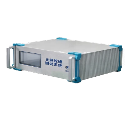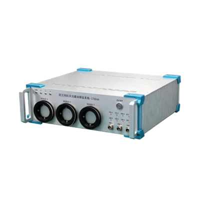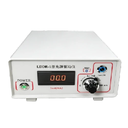
LDDR1 SLD Controller
Adjustable high-stability constant current output
PID precision temperature control
Description
Key Features
- Adjustable high-stability constant current output
- PID precision temperature control
Applications
- For R&D, testing, and production of laser diode modules
Product Introduction
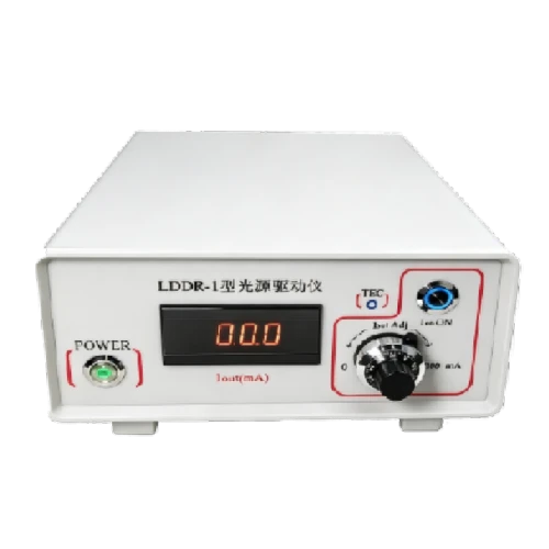
Company LDDR1 SLD light source driver consists of an adjustable constant current source, TEC temperature control system, safety monitoring microcontroller, power supply, and XL-BL01 adapter. The constant current source supplies DC current for full-range laser output power adjustment via a panel knob with digital display. The TEC temperature control system achieves precise chip temperature control through a thermoelectric cooler and temperature sensing resistor, ensuring long-term wavelength and power stability.
Unique Technology
Company is a high-tech enterprise with full closed-loop capabilities from fiber winding equipment and coils to FOGs, fiber/MEMS inertial products, IMU circuits, software, and test equipment. End-to-end process control improves quality and reduces costs. Operating under ISO9001 with strict processes, it ensures product reliability and consistency.
Parameters
LDDR1 SLD Controller Performance Specifications
|
Parameter |
Parameters |
|
Performance Specifications |
|
|
Output Current |
0-200mA |
|
Output Current Stability Over Time |
≤0.1% (1 hour), (test conditions: 30 min warm-up, 100 mA, 25±3 °C) |
|
Modulation Mode |
DC |
|
Temperature Control Range |
(-45 to +75) °C, (test conditions: laser diode) |
|
Built-in Temp. Control Bridge Resistance |
10±0.3 KΩ |
|
Max. TEC Current (factory set) |
>1 A, (test conditions: RL 2.4 Ω ±2%, 2 W) |
|
Max. TEC Voltage (factory set) |
2.5±0.2 V, (test conditions: RL 2.4 Ω ±2%, 2 W) |
|
Temperature Control Mode |
PID |
|
Laser Diode Drive Current Indication Error |
≤ ±1%±0.5mA |
|
Electrical/Mechanical Interface |
|
|
Dimensions/Weight |
~ (300 × 250 × 100 mm) / approx. 2 kg |
|
Power Supply |
220V, 50Hz, AC |
Introduction
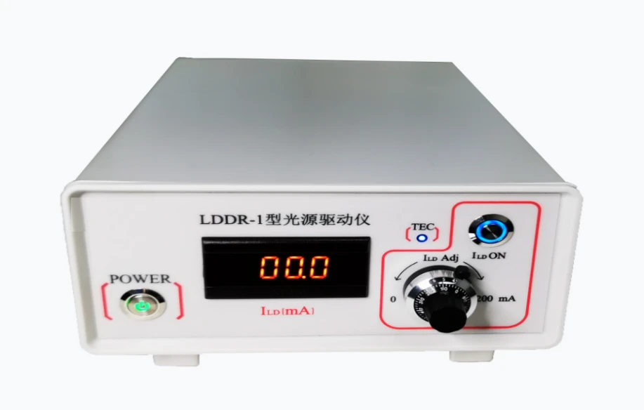
Name: LDDR1 SLD Controller
Application: LDDR1 can be used for the R&D, test, and production of SLD
Function: Output a highly stable DC current signal with adjustable amplitude for stable operation of the laser diode; Output TEC working current regulated by PID controller to achieve precise constant temperature control of laser diode chips
2.Composition, Working mode, and Usage methodLDDR1 controller host
Composition
The LDDR1 mainly consists of an adjustable constant current source, TEC temperature control system, built-in safety startup and monitoring microcomputer, overall power supply and control panel, XL-BL01 laser diode adapter and special cable, XL-PT01 special cable.
Adjustable constant current source
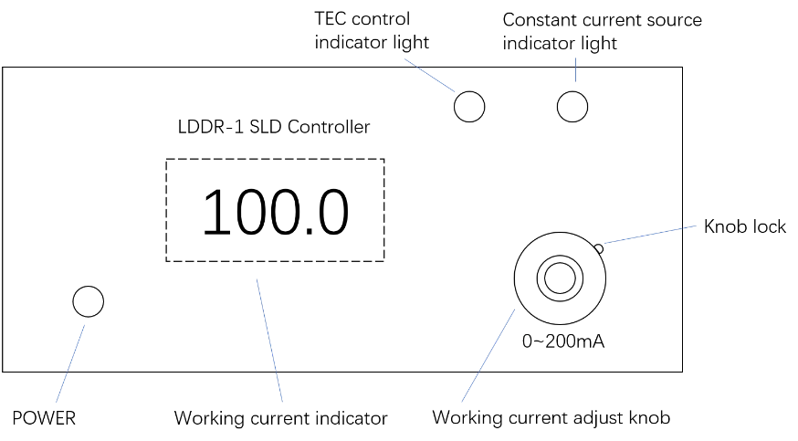
Provides stable DC working current to the laser diode module, achieving control and full amplitude adjustment of laser output power. The current amplitude can be continuously adjusted by the panel knob and displayed in digital form on the instrument panel. The design and implementation of electronic process technology effectively overcomes the influence of factors such as time, environmental temperature and humidity, and AC power supply voltage on the output current amplitude of adjustable constant current sources, and achieves the basic stable characteristics of laser output amplitude. The output control switch on the panel controls the effective (yellow indicator light on) and off (yellow indicator light off) state of the constant current source.
TEC temperature control system
It mainly consists of the thermoelectric cooler (TEC), thermistor, other sturctural components, and host electronic circuits in the controlled laser diode assembly. It can realize precise temperature control of laser diode chips and ensure long-term stability and termperature stability of output laser wavelength and power.
Built-in safety startup and monitoring microcomputer
After the power is turned on, it will control the startup sequence of each sub-system, monitor the thermal status of laser diode chip so as to protect the chip. The microcomputer will turn off the output current of constant current source, and turn on the TEC controller, monitor the normal range of present temperature that should be reached by temperature controller, and at this time, the TEC temperature indicator light (blue) on the panel flashes slowly for about 2 to 10 seconds. if the temperature control is normal, the TEC controller remains turned on, the internal output current switch is turned on, and the TEC temperature control indicator light continues to light up; if the temperature control is abnormal, the program will turn off the TEC controller, internal output current will be turned off, and the TEC temperature contrl indicator light will flash quickly (about 2 timer/second) to indicate an abnormal state. The program also monitors the temperature control status during laser output. When the temperature exceeds the set range, the program will turn off the TEC controller and the internal output current, and the TEC temperature control light flashes quickly, indicating an abnormal state.
Panel
XL-BL01 SDL adapter and cable
XL-BL01 SLD adapter
The XL-BL01 laser diode adapter is a 14-pin butterfly shaped package, no insertion and extraction force, crimping, and buckle locking connector. Laser diode components can be connected to 8-pin ~ 14-pin butterfly package connector. The comprehensively designed adapter cover has a low contact thermal resistance with the laser diode base, ensuring the reliable operation of the laser diode under extreme conditions such as high temperature.
XL-BL01 cable
The XL-BL01 cable is equipped with high-temperature resistant wires and high-temperature shielded wires. It has a wide working temperature range and good anti-interference capability.
Usage method
The connection between the XL-BL01 cable and the host socket is shown in the following figure:
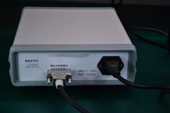
Connection between XL-BL01 laser diode adapter and XL-BL01 cable:
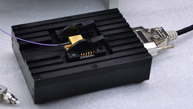
Installation of laser diode components:
Flip the two buckle plates (left figure below) on the XL-BL01 laser diode adapter to the left and the two crimp plates (right figure below) to the right, as shown in the following figure:
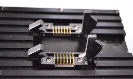
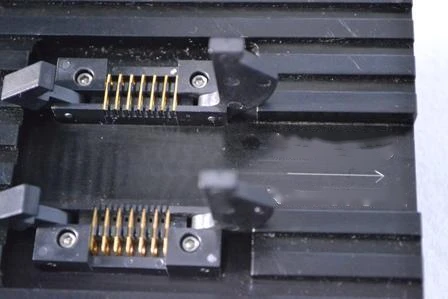
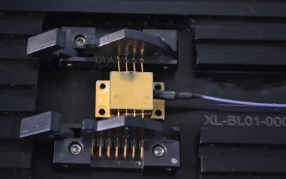
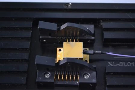
Align the fiber direction of the laser diode assembly with the arrow mark on the surface of the adapter. Apply an appropriate amount of thermal conductive silicone grease to the base of the laser diode assembly, align the lead of the laser diode assembly correctly with the slot of the adapter contact point, push the crimping plate to the left on the lead of the laser diode assembly, and gently press it down. Push the two buckle plates to the right to complete the locking process.
ATTENTION!
The XL-BL01 laser diode adapter has an internal electrical connection that is factory configured according to commonly used 8-pin butterfly components. When placing the 8Pin laser diode assembly onto the adapter, the assembly should be placed next to the edge to achieve correct pin connection. The fiber direction of the laser diode should be consistent with the direction of the arrow mark on the surface of the adapter. The 8-pin laser diode should be placed on the right side as shown in the following figure.
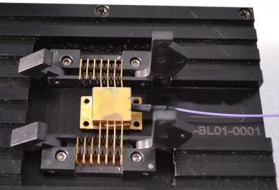
The pin definition of XL-BL01 laser diode adapter
The pin numbers on the upper row of the XL-BL01 laser diode adapter (from right to left in the figure above) are: 1#~7#, and the pin numbers on the lower row (from right to left) are: 14#~8#.
Factory set adapter internal connection definition and commonly used laser diode pin comparison table
|
Host pin |
Host pin definition |
SLD pin |
SLD pin definition |
Host pin |
Host pin definition |
SLD pin |
SLD pin definition |
|
1# |
TEC cooler + |
1# |
TEC cooler + |
14# |
TEC cooler- |
8# |
TEC cooler- |
|
2# |
Thermistor1 |
2# |
Thermistor1 |
13# |
NC |
7# |
NC |
|
3# |
Thermistor2 |
3# |
Thermistor2 |
12# |
NC |
6# |
NC |
|
4# |
SLD anode+ |
4# |
SLD anode+ |
11# |
SLD cathode- |
5# |
SLD cathode- |
|
5# |
-- |
-- |
-- |
10# |
-- |
-- |
-- |
|
6# |
-- |
-- |
-- |
9# |
-- |
-- |
-- |
|
7# |
-- |
-- |
-- |
8# |
-- |
-- |
-- |
XL-PT01 special cable
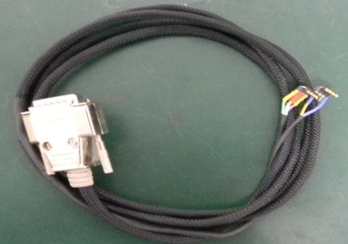
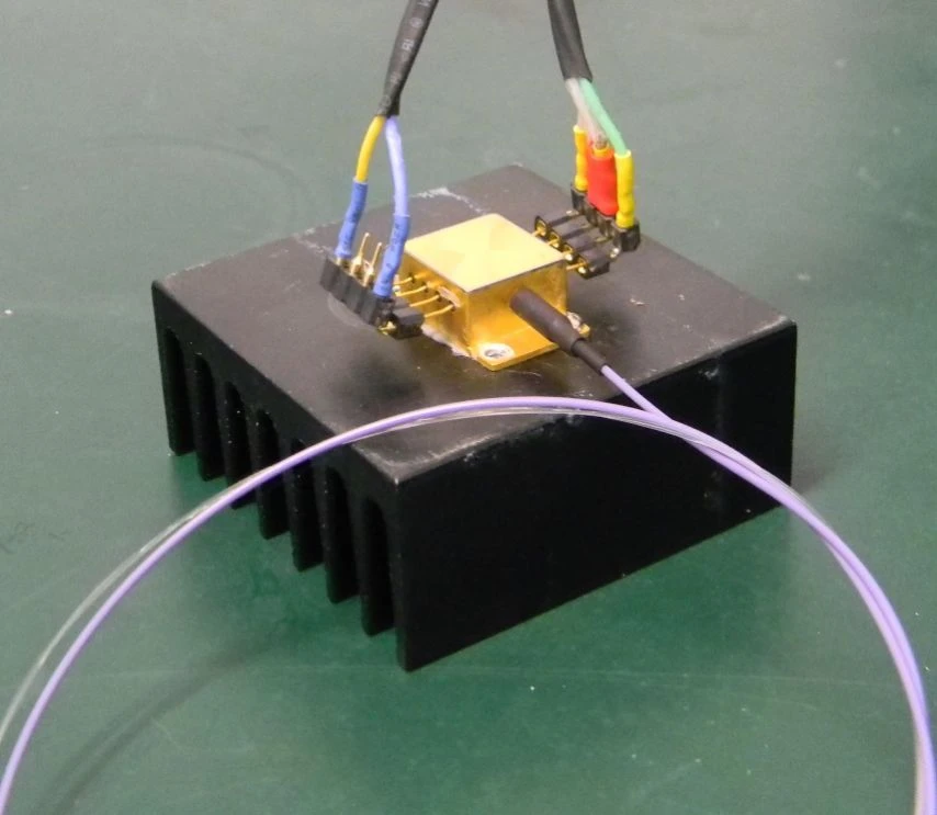
When using XL-PT01 special cable, additional heat sinks or heat dissipation metal plates must be installed. The higher the temperature of the environment, the larger the size of the heat sink (air contact area). Coat the base of the laser diode assembly with an appropriate amount of thermal conductive silicone grease or place a thermal conductive film on it to effectively dissipate the heat emitted from the bottom plane of the laser diode through the heat sink. The connection between XL-PT01 special cable and SLD light source device is shown in the following figure:
|
XL-PT01 cable pin |
SLD pin |
Host rear panel DB15 pin |
XL-PT01 cable pin |
SLD pin |
Host rear panel DB15 pin |
|
1# |
TEC+ |
7#/8# TEC+ |
8# |
TEC- |
5#/6# TEC- |
|
2# |
Thermistor |
14# Thermistor |
7# |
NC |
-- |
|
3# |
Thermistor |
15# Thermistor |
6# |
NC |
-- |
|
4# |
SLD anode |
3#/4# SLD anode |
5# |
SLD cathode |
1#/2# SLD cathode |
Power fuse
Fuse specifications: 0.5A/250V 20mm
Fuse box: one fuse in use, one backup fuse
Insert a screwdriver into the horizontal slot above the fuse box and pry out the fuse box outwards.
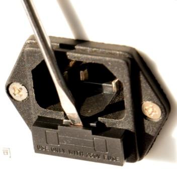
Backup fuse inside the square hole
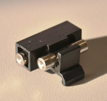
Removing or pressing in the fuse
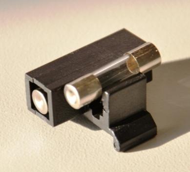
Technical characteristics
Working environment
Temperature: 5°C ~40°C
Relative humidity: 15%~85%RH
High electromagnetic: Avoid
Sunshine, water, dust, vibration: Avoid
Ventilation and heat dissipation: should be good
Power supply: AC, 220V, 50Hz, total grounding resistance* ≤2Ω, working power supply collinear load ≤3KW (switching frequency<10 times/hour)
*The total resistance value from the power socket contact piont to the ground reference point (including the contact resistance between the socket contact and the clean surface plug)
Storage environment
Temperature: -15°C ~55°C
Relative humidity: 15%~95%RH
High electromagnetic: Avoid
Corrosive gases: Avoid
Specifications
|
Parameters |
Units |
Test conditions |
Specifications |
|
Output current range |
mA |
0- 200 |
|
|
Output current time stability |
% |
preheating for 30min,100mA,25±3℃ |
< 0.1(hour) |
|
Modulation method |
- |
- |
DC |
|
Temperature control range |
℃ |
Laser diode |
-45~+75 |
|
Built-in bridge resistance for temperature control |
KΩ |
10±0.3 |
|
|
Maximum TEC current (set by the factory) |
A |
RL:2.4Ω±2%-2W |
>1 |
|
Maximum TEC voltage (set by the factory) |
V |
RL:2.4Ω±2%-2W |
2.5±0.2 |
|
Temperature control method |
PID |
||
|
Laser diode driving current indication error |
≤±1%±0.5mA |
||
|
Size |
mm |
300´250´100 |
|
|
Weight |
kg |
approx. 2 |
Installation and usage precautions
This product uses a single-phase three wire standard power cord, and a correctly connected single-phase three wire (hole) power socket must be used to ensure the safety of the user and this product. The N: neutral wire, L: live wire, and E: ground wire of the power socket must be configured according to the standard, and any incorrectly configured power socket cannot be used! Before connecting the power cord of the device to the AC power socket, you can refer to the markings on the power cord plug to check and confirm whether the AC power socket wiring is correct. E: The ground wire is internally connected to the chassis casing and most accessible metal components to prevent safety hazards such as internal leakage. Do not use a two wire power cord! Do not use a two hole power socket! Do not replace or use non-standard, other specifications, or unqualified power cords at will.
Regular inspection of power cords is an effective measure to prevent personal electric shock and fire:
a. New power cords should be checked: the connection resistances between terminals E of the power cords should be ≤ 1 Ω, the connection resistances of between L of the power cords should be ≤ 1 Ω, the connection resistances of between N of the power cords should be ≤ 1 Ω(after deducting the lead resistance of the ohmmeter); When bending and twisting the power cord near both ends and other parts, there should be no disconnection phenomenon; There should be no interconnection between terminals with different names. Otherwise, a new and qualified standard power cord should be replaced.
b. For power cords that have been plugged and unplugged at both ends of the power cord for a total of no more than 40 times during use, and that have been stretched and twisted less than 60 times, and that are placed in a non vibration environment, after 11 months of use, the connection resistance between the E terminals of the power cord should be checked: the connection resistance between the E terminals of the power cord should be ≤ 1 Ω (after deducting the lead resistance of the ohmmeter), and it should be judged as qualified; When bending and twisting the power cord near both ends and other parts, there should be no disconnection phenomenon. Otherwise, a new and qualified standard power cord should be replaced.
c. For power cords that have been plugged and unplugged at both ends of the power cord for a total of no more than 40 times during use, and that have been stretched and twisted less than 60 times, and that are placed in a non vibration environment, after 6 months of use, the connection resistance between the E terminals of the power cord should be checked: the connection resistance between the E terminals of the power cord should be ≤ 1 Ω (after deducting the lead resistance of the ohmmeter), and it should be judged as qualified; When bending and twisting the power cord near both ends and other parts, there should be no disconnection phenomenon. Otherwise, a new and qualified standard power cord should be replaced.
The power switch of the host panel must be turned to the "off" position before connecting or unplugging the power cord! Otherwise, it is easy to damage the laser and the host.
When the host is connected to the power supply, the "on" and "off" conversion interval of the power switch should be greater than 10 seconds.
During human activities, high-voltage static electricity generated by friction, compression, and other factors can easily cause hidden damage to the laser diode and host. Wear an electrostatic protective wrist strap when touching the laser diode! When moving the host without any electrostatic protection measures, avoid placing your fingers near the back panel socket, display components (indicator lights, ammeters), cables, and adapters (when connected to the host)! Avoid placing and working in strong alternating or static electric fields such as ion fans!
Before placing the laser diode in the adapter or connecting it to the host, the output control switch on the host panel must be placed in the "off" position (the output indicator light does not light up)! It is necessary to ensure that the definition of the host connection pin matches the definition of the laser diode pin correctly (refer to the comparison table "Factory set adapter internal connection definition and commonly used laser diode pin comparison table")! To avoid damaging the laser diode components!
When using this product, please pay attention to the ventilation and heat dissipation of the entire device and the laser diode adapter, which is conducive to the stable and reliable operation of the entire device and the laser diode.
Hot Tags: lddr1 sld controller, China lddr1 sld controller manufacturers, factory