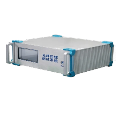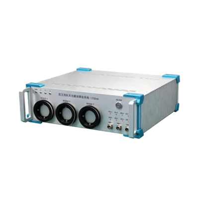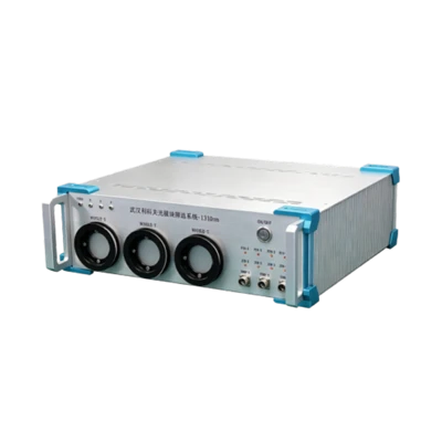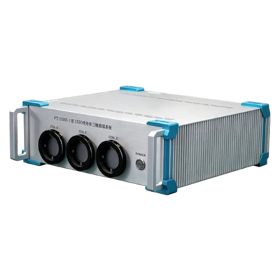
FMTP Fiber Coil Multifunction Test Platform
Easy operation
Multiple tests in one session
Automatic test report generation
Description
Key Features
- Integrated OTDR, extinction ratio testing, and red light detection
- Easy operation
- Multiple tests in one session
- Automatic test report generation
Applications
- Fiber coil testing
- PM or single-mode fiber inspection
Product Introduction
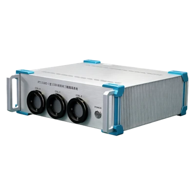
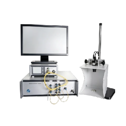
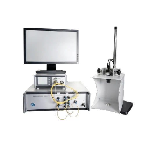
Company FMTP fiber coil multifunction test platform integrates OTDR, extinction ratio testing, and red light detection. It completes fiber coil length, loss, crosstalk, and red light inspection in a single station, automatically generates test reports via host software, and supports networked storage to designated databases. Features include simple and fast operation, high automation, and automatic report generation with archiving.
Unique Technology
Company is a high-tech enterprise with full closed-loop capabilities from fiber winding equipment and coils to FOGs, fiber/MEMS inertial products, IMU circuits, software, and test equipment. End-to-end process control improves quality and reduces costs. Operating under ISO9001 with strict processes, it ensures product reliability and consistency.
Parameters
FMTP Fiber Coil Multifunction Test Platform Performance Specifications
|
Automatic Polarization Extinction Ratio Tester |
||
|
Model |
Model A |
Model B |
|
Wavelength Range (nm) |
600~1200 |
1200~1700 |
|
Max. Input Power (dBm) |
+10 |
|
|
Input Power Range (dBm) |
-40~+10 |
-40~+10 |
|
PER Maximum (dB) |
40 |
50 |
|
PER Dynamic Range (dBm, dB) |
-30~+10: 40 -40~-30: 30 |
-30~+10: 50 -40~-30: 40 |
|
PER Resolution (dB, dB) |
<10: 0.001 ≥10: 0.01 |
|
|
PER Accuracy (dB, dB) |
PER≤2: ≤±0.1 PER<30: ≤±0.3 PER≥30: <±0.1 |
|
|
Polarizer Input Type |
Broadband SLED or ASE source |
|
|
Polarization Angle Resolution (°) |
0.11 |
|
|
Polarization Angle Resolution (°) |
<±0.45 |
|
|
Measurement Speed (s) |
0.25 |
|
|
Measurement Connector Type |
FC/PC (multiple options) |
|
|
Polarizer Calibration Wavelength (nm) |
850/1310 |
|
|
Polarizer Extinction Ratio Range (dB) |
40 |
|
|
Polarizer Connector Type |
FC/PC (single option only) |
|
|
Polarizer Insertion Loss (dB) |
5X(excluding polarizer) |
|
|
Polarization Time (s) |
0~10 |
|
|
Low-Polarization Broadband Light Source |
||
|
Specifications |
SLED Low-Polarization Source |
|
|
Max. Output Power (mW) |
2, 5, 10 or custom |
|
|
Polarization Extinction Ratio (dB) |
≤0.1 |
|
|
Center Wavelength (nm) |
1310/1550/850/980/1064 or custom |
|
|
Spectral Width (nm) |
40~50 |
|
|
Output Power Stability (dB) |
±0.05 (15min/1mW, 25℃)(850/1310/1550 nm only) ±0.08 (8Hour/1mW, 25℃)(850/1310/1550 nm only) |
|
|
Laser Type |
SLED |
|
|
Output Return Loss (dB) |
>45 |
|
|
TEC Stability (°C) |
±0.1 |
|
|
TEC Operating Range (°C) |
10~60 |
|
|
Applicable Fiber Type |
SM: 9/125, MM: 50/125 or 62.5/125 |
|
|
Light Source Connector |
FC/APC (FC/PC optional) |
|
FMTP Fiber Coil Multifunction Test Platform Performance Specifications
|
Multi-Channel Optical Switch Module |
||||
|
Optical Switch Type |
Mechanical |
MEMS |
||
|
Optical Switch Channels |
Supports 2–48 channels |
|||
|
Optical Interface |
FC/APC or PC |
|||
|
Fiber Type |
9/125 or 50/125 or 62.5/125 |
|||
|
Operating Wavelength (nm) |
SM: 1260–1650 full band / MM: 850 & 1300 |
|||
|
Insertion Loss (dB) |
<1.2, typical 1 |
≤1.0 |
||
|
Switching Time |
SM: ≤10 ms, ≤1 ms / MM: ≤15 ms |
|||
|
Repeatability (dB) |
≤±0.05 |
≤0.02 |
||
|
Lifetime (cycles) |
≥3×10^7 |
≥10^9 |
||
|
High-Speed Power Meter Module |
||||
|
Wavelength Range (nm) |
850~1700 |
|||
|
Calibration Wavelength (nm) |
850, 1300, 1310, 1490, 1550, 1625 |
|||
|
Probe Type |
InGaAs |
|||
|
Detector Size (mm) |
Ф2 |
|||
|
Measurement Range (dBm, dB) |
A: +10~-60, C: +25~-60 |
|||
|
Linearity (dB, dBm) |
±0.04(A: +10~-50) |
|||
|
Sampling Rate (ksps) |
10 |
|||
|
Uncertainty (%) |
±3 (A: +10~-60dBm, C: +25~-45dB) |
|||
|
Measurement Unit |
dBm/dB |
|||
|
Communication Interface |
RS232 |
|||
|
Analog Voltage (V) |
0~2.5 |
|||
|
Operating Temperature (℃) |
-5~+40 |
|||
|
Storage Temperature (℃) |
-25~+70 |
|||
|
Operating Power (V) |
DC 9~12 |
|||
|
Wavelength Range (nm) |
850~1700nm |
|||
|
OTDR Module |
||||
|
Model |
JW3302M-24/24-FP |
JW3302M-30/28-FP |
JW3302M-30-FP |
|
|
Wavelength (nm) |
1310/1550 |
1310/1550 |
1625 |
|
|
Dynamic Range (dB) |
26/24 |
30/28 |
30 |
|
|
Pulse Width (ns) |
10/20/50/100/200/500/1μs/2μs /10μs /20μs |
|||
|
Reflection Dead Zone (m) |
≤1.8 |
|||
|
Attenuation Dead Zone (m) |
≤10 |
|||
|
Sampling Resolution (m) |
0.32 to 5 |
|||
|
Distance Uncertainty (m) |
±(1 m + 0.005% × distance + sample interval) |
|||
|
Distance Range (km) |
1 to 80 |
1 to 120 |
1 to 160 |
|
|
Measurement Duration |
5s, 15s, 30s, 1min, 2min, 3min |
|||
Introduction
FMTP Fiber Coil Multifunction Test Platform integrates OTDR, polarization extinction ratio test and light leakage (leaking light indicates damage to the coil's fiber) check functions. The user can measure the coil's length, loss, PER, and check whether the coil's fiber is leaking light simultaneously on this platform, and the test reports can be automatically generated through the upper computer software, which can be networked and stored in a database. It has the advantages of simple and fast operation, automatic generation of reports and storage.
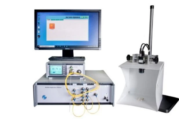
Composition
Host computer
Extinction ratio meter with automatic polarization
Low-DOP (degree of polarization) broadband light source, wavelength 1310/1550nm
Red light module
Two optical switches
OTDR
External high-speed light power meter probe
Camera
Specifications
Extinction ratio meter with automatic polarization
Description
The extinction ratio meter is a professional equipment used for PER test of polarizaiton maintaining fiber, device and connector, polarization degree test of light source. The upper computer software has powerful functions and is easy to operate. On the basis of the previous, an automatic polarization function has been added, making it faster and more convenient for customers to use.
Features
Large PER dynamic range
High precision and stability
Fast testing
Automatic control of polarizer, fast speed
Support RS232 interface
Support insertion loss test
Support optical axis angle test of polarization maintaining fiber
Specifications
Low polarization broadband light source
|
Type |
A |
B |
|
Wavelength range |
600~1200nm |
1200~1700nm |
|
Maximum input power |
+10dBm |
|
|
Input power range |
-40~+10dBm |
-40~+10dBm |
|
PER maximum value |
40dB |
50dB |
|
PER dynamic range |
-30~+10dBm:40dB -40~-30dBm: 30dB |
-30~+10dBm:50dB -40~-30dBm: 40dB |
|
PER resolution |
<10dB: 0.001dB ≥10dB: 0.01dB |
|
|
PER accuracy |
PER≤2dB:≤±0.1dB PER<30dB:≤±0.3dB PER≥30dB:<±0.1dB |
|
|
Polarizer input light source type |
SLED or ASE |
|
|
Polarization angle resolution |
0.11° |
|
|
Polarization angle accuracy |
<±0.45° |
|
|
Measurement speed |
0.25s |
|
|
Connector |
FC/PC(customizable) |
|
|
Polarizer calibration wavelength |
850nm/1310nm |
|
|
Extinction ratio range of polarizer |
40dB |
|
|
Connector of polarizer |
FC/PC |
|
|
Polarizer insertion loss |
5dB(without polaroid) |
|
|
Polarize time |
0~10s |
|
Description
SLED low polarization light source has a low polarization extinction ratio, which can meet the production and testing needs of polarization maintaining devices. It has high output power stability and wavelength stability, and can meet multiple customer needs. It can achieve a single wavelength output, making it an ideal instrument for scientific research and production. SLED can be widely used in scientific research, production, and engineering in fields such as optical communication, optical transmission, and fiber optic sensing.
Features
Low polariztion extinction ratio
High output power stability: up to 0.01dB
Output power is adjustable
High wavelength stability
High accuracy APC and ATC circuits
LCD display status parameters
Optional with 1~4 center wavelengths and up to 4 output ports
Provide internal and external modulation modes
Specifications
|
Parameters |
SLED low polarization light source |
|
Maximum output power /mW |
2, 5, 10 or customized |
|
Polarization extinction ratio/ dB |
≤0.1dB |
|
Center wavelength /nm |
1310/1550/850/980/1064nmo or customized |
|
Spectral width /nm |
40~50nm |
|
Output power stability /dB |
±0.05(15min/1mW, 25℃)(only 850/1310/1550nm) ±0.08(8Hour/1mW, 25℃)(only 850/1310/1550nm) |
|
Laser type |
SLED |
|
Return loss /dB |
>45 |
|
TEC stablility /℃ |
±0.1 |
|
TEC working temperature range /℃ |
10~60 |
|
Fiber type |
SM:9/125, MM:50/125 or 62/125 |
|
Light source connector |
FC/APC (FC/PC optional) |
|
Temperature adjustment accuracy /℃ |
0.01 |
Multi-channel optical switch module
Description
It is mainly used in optical switching devices and systems to achieve all optical layer routing, wavelength selection, and self-healing protection functions. According to customer needs, it can be configured with 1×2, 1×4, 1×8, 1×24 channels and other customized channel numbers, and can be combined with other modular products of our company.
Features
Wide wavelength range
Fast switching speed
Low insertion loss and high return loss
No glue in the optical path, it is stable and reliable
The maximum number of optical swithc paths can reach 1×256
Specifications
High speed power meter module
|
Optical switch type |
Mechanical |
MEMS |
|
Optical switch channel |
Support 2~48 channels |
|
|
Optical connector |
FC/APC or PC |
|
|
Fiber type |
9/125 or 50/125 or 62.5/125 |
|
|
Working wavelength |
single mode:1260~1650nm full band multi mode:850&1300nm |
|
|
Insertion loss |
<1.2dB, typical 1dB |
≤1.0dB |
|
Switch time |
single mode:≤10m,≤1ms multi mode:≤15m |
|
|
Repeatablility |
≤±0.05dB |
≤0.02dB |
|
Life |
≥3×10^7 times |
≥10^9 times |
(1) Description
The external probe optical power meter provides accurate power measurement through a large area detector inside the remote probe, which has the advantage of flexible positioning. Its functions include the average time setting from 100μs to 1s, automatic power range, monitoring of minimum and maximum values, and record up to 20000 samples. Fiber optic adapters can be used for common connector types, including MT ribbon fiber optic connectors and bare fiber clamps. The D-type adapter is a magnetic fixed type, which facilitates quick replacement of the adapter. The probe also includes a detachable adapter ring for threaded adapters. Detection devices with temperature control can be selected to make the test data more stable and accurate.
(2) Features
a. Support RS232 serial communication and real-time communication
b. The module can communicate with the upper computer independently, making it easy to use
c. Large dynamic range
d. Optional test range
e. Storage depth of 20000 data points
f. The maximum sampling rate is 10kps, and the sampling rate can be set
g. Quick start and high measurement accuracy
h. Support triggering storage
i. Equipped with analog voltage output function
(3) Specifications
|
Parameters |
Specifications |
|
Wavelength range |
850~1700nm |
|
Calibration wavelength |
850, 1300, 1310, 1490, 1550, 1625nm |
|
Probe type |
InGaAs |
|
Probe size |
Ф2mm |
|
Measurement range |
A: +10~-60dBm, C: +25~-60dB |
|
Linearity |
±0.04dB(A: +10~-50dBm) |
|
Sampling rate |
10ksps |
|
Uncertainty |
±3%(A: +10~-60dBm, C: +25~-45dB) |
|
Measurement unit |
dBm/dB |
|
Communication interface |
RS232 |
|
Analog voltage |
0~2.5V |
|
Working temperature |
-5~+40℃ |
|
Storage temperature |
-25~+70℃ |
|
Power supply |
DC 9~12V |
OTDR (optical time domain reflectometer)
|
Type |
JW3302M-24/24-FP |
JW3302M-30/28-FP |
JW3302M-30-FP |
|
Wavelength /nm |
1310/1550 |
1310/1550 |
1625 |
|
Dynamic range /dB |
26/24 |
30/28 |
30 |
|
Pulse width /ns |
10/20/50/100/200/500/1μs/2μs /10μs /20μs |
||
|
Reflection blind zone /m |
≤1.8 |
||
|
Attenuation blind zone /m |
≤10 |
||
|
Sampling resolution /m |
0.32 to 5 |
||
|
Distance uncertainty /m |
± (1m+0.005%×distance+sampling interval) |
||
|
Distance range /km |
1 to 80 |
1 to 120 |
1 to 160 |
|
Measurement duration |
5s,15s,30s,1min,2min,3min |
||
Hot Tags: fmtp fiber coil multifunction test platform, China fmtp fiber coil multifunction test platform manufacturers, factory