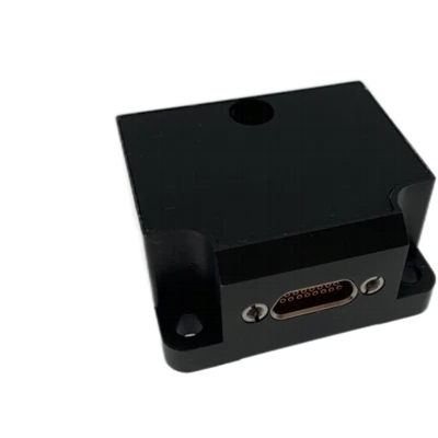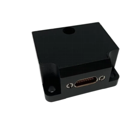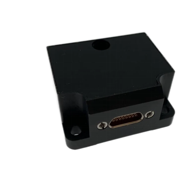
MTG300A MEMS Gyro
2 kHz high-speed sampling
Excellent resistance to severe mechanical environments
Support for in-field software upgrade
Description
Main Features
- 100% domestically sourced electronic components
- Compact outline, light weight and low power consumption
- 2 kHz high-speed sampling
- Excellent resistance to severe mechanical environments
- Support for in-field software upgrade
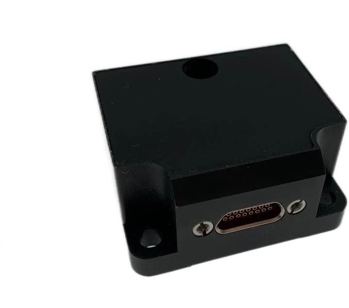
Application Fields
 Satellite stabilization and attitude control
Product Overview
The MTG300A MEMS three-axis gyro assembly is a high-reliability, cost-effective 3-axis MEMS gyro assembly, applicable to navigation and control fields of low-to-medium Earth orbit satellites. Assembly integrates high-performance MEMS gyroscopes inside an independent mechanical housing. The built-in gyroscopes adopt domestically manufactured MEMS inertial sensor technology reaching advanced industry level.The three-axis MEMS gyroscope senses the angular motion of the carrier. Full-temperature compensation for Bias, scale factor and non-orthogonality error is implemented inside the system, enabling sustained high measurement accuracy during long-term operation.
Unique Technology
Company is a high-tech enterprise with full closed-loop capabilities from fiber winding to FOGs, fiber/MEMS inertial products, IMU circuits, software, and test equipment. End-to-end process control improves quality and reduces costs. Operating under ISO9001, it ensures reliability and consistency. INS plays a critical role in intelligent coal mining, with FOG as the key component.The MTG300A MEMS three-axis gyro assembly adopts an aluminum alloy mechanical housing, featuring light weight, high structural strength, and outstanding vibration & shock resistance.
MTG300A Tri-axis MEMS Gyro Combination
MTG300A Tri-axis MEMS Gyro Combination Performance Parameters
|
Parameter |
Technical Index |
|
Gyroscope |
|
|
Measurement Range (°/s) |
±100 |
|
Full-Temperature Bias (°/h) |
≤5 |
|
Bias Stability (°/h, 10s averaging window) |
≤0.1 |
|
Bias Stability (°/h, 100s averaging window) |
≤0.05 |
|
Bias Instability (°/h, Allan variance method, typical) |
≤0.02 |
|
Bias Repeatability (°/h) |
≤0.1 |
|
Angular Random Walk (°/√h) |
≤0.005 |
|
g-Dependent Drift (°/h/g) |
≤0.5 |
|
Scale Factor Nonlinearity (ppm) |
≤150 |
|
Bandwidth (Hz) |
≥12 |
|
Electrical & Mechanical Interfaces |
|
|
Supply Voltage (V) |
5~12 (ripple ≤100 mV) |
|
Power Consumption (W) |
≤1.5 |
|
Startup Time (s) |
≤2 |
|
Communication Interface |
1 channel RS-422 |
|
Data Update Rate |
Polling response output, max. 200 Hz |
|
Overall Dimension (mm×mm×mm) |
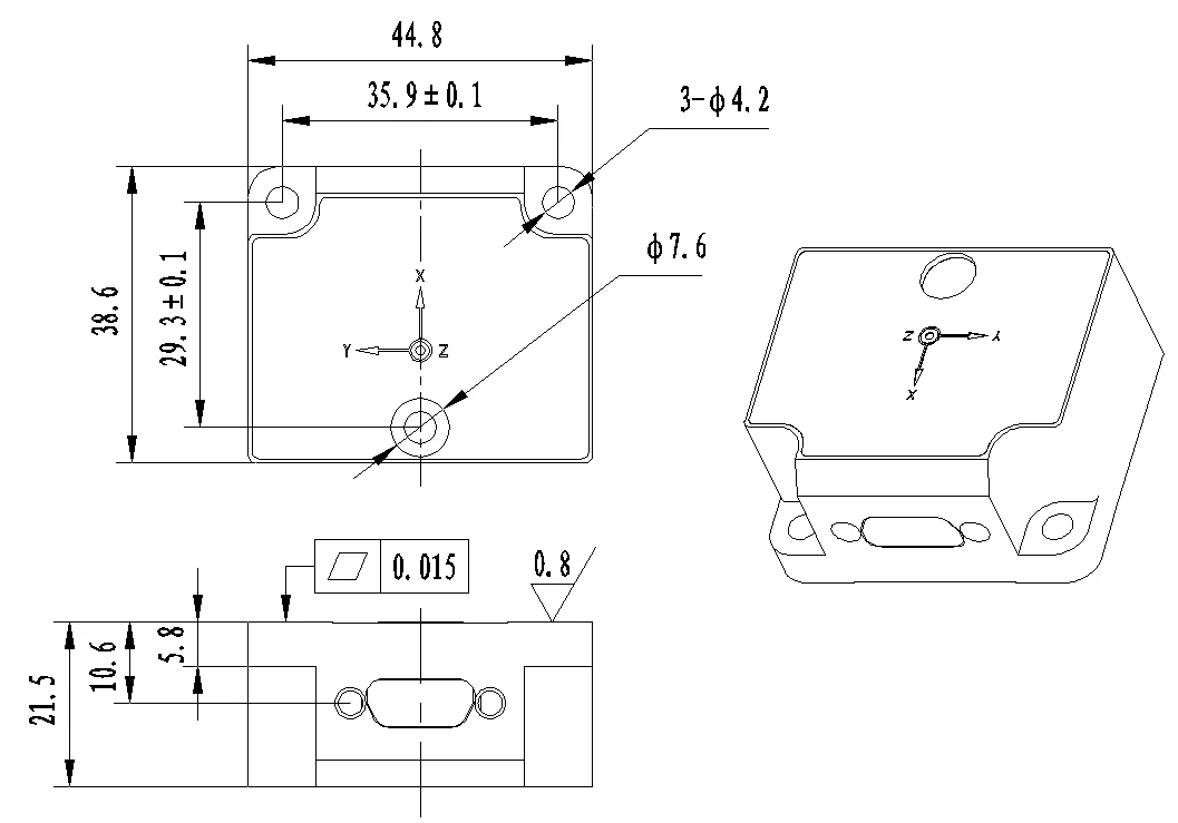
44.8×38.6×21.5 |
|
Weight (g) |
≤60 |
|
Operating Environment |
|
|
Operating Temperature (℃) |
-40 ~ 85 |
|
Storage Temperature (℃) |
-55 ~ 85 |
|
Vibration |
7.72 g (RMS) |
|
Shock |
500 g / 1 ms pulse |
Dimensional Drawing
Product Introduction
Product Brief
The MTG300A MEMS three-axis gyro assembly is a high-reliability, cost-effective 3-axis MEMS gyro assembly, applicable to navigation and control fields of low-to-medium Earth orbit satellites. The MTG300A series MEMS three-axis gyro assembly integrates high-performance MEMS gyroscopes inside an independent mechanical housing. The built-in gyroscopes adopt domestically manufactured MEMS inertial sensor technology reaching advanced industry level. All electronic components inside the system are 100% domestically sourced. The three-axis MEMS gyroscope senses the angular motion of the carrier. Full-temperature compensation for Bias, scale factor and non-orthogonality error is implemented inside the system, enabling sustained high measurement accuracy during long-term operation.
Product Features
- 100% domestically sourced electronic components
- Compact outline, light weight and low power consumption
- Full-temperature calibration and compensation ranging from -40℃ to +80℃
- 2 kHz high-speed sampling
- Excellent resistance to severe mechanical environments
- Support for in-field software upgrade
Application Fields
- Satellite stabilization and attitude control
Technical Parameters
Table 1 Performance Parameters of MTG300A MEMS Three-Axis Gyro Assembly
|
Parameter |
Technical Index |
|
Gyroscope |
|
|
Measurement Range (°/s) |
±100 |
|
Full-Temperature Bias (°/h) |
≤5 |
|
Bias Stability (°/h, 10s averaging window) |
≤0.1 |
|
Bias Stability (°/h, 100s averaging window) |
≤0.05 |
|
Bias Instability (°/h, Allan variance method, typical) |
≤0.02 |
|
Bias Repeatability (°/h) |
≤0.1 |
|
Angular Random Walk (°/√h) |
≤0.005 |
|
g-Dependent Drift (°/h/g) |
≤0.5 |
|
Scale Factor Nonlinearity (ppm) |
≤150 |
|
Bandwidth (Hz) |
≥12 |
|
Electrical & Mechanical Interfaces |
|
|
Supply Voltage (V) |
5~12 (ripple ≤100 mV) |
|
Power Consumption (W) |
≤1.5 |
|
Startup Time (s) |
≤2 |
|
Communication Interface |
1 channel RS-422 |
|
Data Update Rate |
Polling response output, max. 200 Hz |
|
Overall Dimension (mm×mm×mm) |
44.8×38.6×21.5 |
|
Weight (g) |
≤60 |
|
Operating Environment |
|
|
Operating Temperature (℃) |
-40 ~ 85 |
|
Storage Temperature (℃) |
-55 ~ 85 |
|
Vibration |
7.72 g (RMS) |
|
Shock |
500 g / 1 ms pulse |
Technical Specifications
Structural Characteristics
The MTG300A MEMS three-axis gyro assembly adopts an aluminum alloy mechanical housing, featuring light weight, high structural strength, and outstanding vibration & shock resistance. The outline dimensions of the unit are shown in Figure 1, and the unit is fixed with 3 M4 screws.
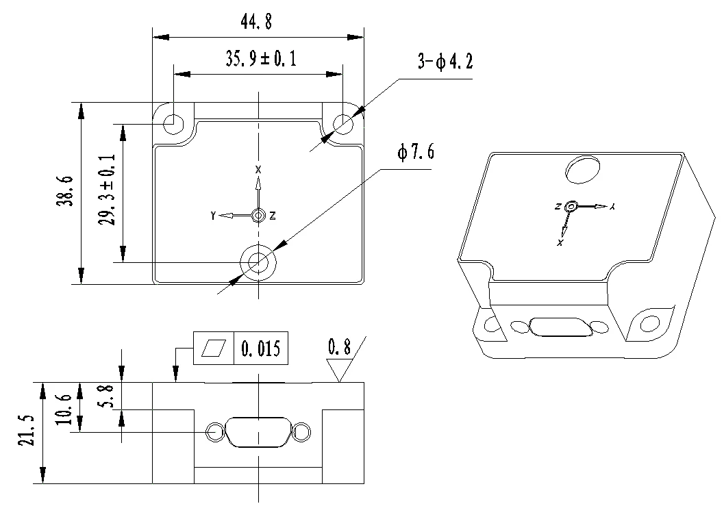
Figure 1 Outline Dimensions
Product Marking and Coordinate Polarity
During installation, the carrier coordinate system of the product shall maintain a fixed geometric relationship with the carrier coordinate system of the host equipment. The carrier coordinate system definition of the MTG300A MEMS three-axis gyro assembly is specified as follows.
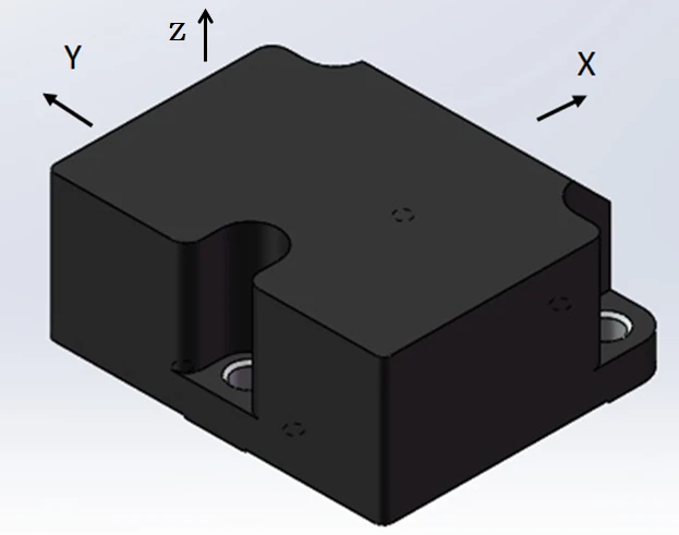
Figure 2 Product Coordinate System
Pin Assignment
The external output connector of the MTG300A MEMS three-axis gyro assembly is J30J-15ZK (mating connector: J30J-15TJL), which provides power supply and external communication for the unit. The pin definitions of the connector are listed in Table 2.
Table 2 External Pin Assignment of MTG300A MEMS Three-Axis Gyro Assembly Connector
|
Pin No. |
Definition |
Remarks |
|
7, 8 |
POWER_IN |
5±0.2 V power input |
|
15 |
GND |
|
|
10 |
RS422 R+ |
RS422 Interface |
|
2 |
RS422 R- |
|
|
9 |
RS422 T+ |
|
|
1 |
RS422 T- |
|
|
3, 12, 13 |
GND |
After the supply voltage drops below the device operating threshold, the power-off holding time t_OFF before re-powering shall not be less than 3 seconds. Insufficient power-off interval will lead to abnormal startup, latch-up or initialization failure of the device.
External Communication Interface
3.4.1 WXGYRO-EB90 Protocol
Data Link Layer
Transmission complies with UART Idle-Line mode, and the frame format of SCI bus is defined as below. The basic transmission unit is a character, with 11 bits per character.

Figure 3 Data Transmission Format
Under Idle-Line transmission mode, each frame occupies 1 byte and all frames are treated as data frames. One SCI data frame is 1 byte (8 bits). The bus remains logic high during idle state. All SCI frames start with a logic-low start bit, followed by frame data transmitted with Least Significant Bit First (LSB First). Detailed frame definition:
- Start bit: 1 bit
- Data bits: 8 bits (b0~b7)
- Stop bit: 1 bit
- Parity bit: Odd parity
- Baud rate: 115200 bps
- For multi-byte transmission, high byte is transmitted prior to low byte by default.
Application Layer
Single Unit Telemetry Data Format
Single unit telemetry data is the response data of each component/module after receiving telemetry request commands from the On-Board Computer (OBC). The detailed format is shown in the table below.
Table 4 Single Unit Telemetry Data Format
|
Byte Index |
Definition |
Description |
|
B0, B1 |
Frame Header |
Fixed value: 0xEB90 |
|
B2, B3 |
Payload Length |
Note 1 |
|
B4 |
Telemetry Data Classification ID |
Note 2 |
|
B5 |
Telemetry Request Command Counter |
Note 3 |
|
B6 |
Valid Command Counter |
Note 4 |
|
B7 |
Invalid Command Counter |
Note 5 |
|
B8 |
Latest Executed Command Code |
Note 6 |
|
B9 ~ B(N-1) |
User-Defined Payload |
Note 7 |
|
BN |
Checksum |
Note 8 |
|
Note: The gyro assembly only supports telemetry request commands without other control commands, so Bytes B6, B7, B8 shall be filled with 0xFF. |
||
- Note 1: Payload Length. Total byte count ranging from Telemetry Data Classification ID (inclusive) to Checksum (inclusive).
- Note 2: Telemetry Data Classification ID. Shall be consistent with the corresponding field in the telemetry request command.
- Note 3: Telemetry Request Command Counter. 1 unsigned byte, increments by 1 upon receiving the matching telemetry request frame sent by the OBC.
- Note 4: Valid Command Counter. 1 unsigned byte, increments by 1 upon receiving a complete valid command excluding telemetry request frames (validated by checksum). Fill with 0xFF for units without remote control commands.
- Note 5: Invalid Command Counter. 1 unsigned byte, counts abnormal received data including wrong frame header, checksum error, unrecognized command code, etc. Fill with 0xFF for units without remote control commands.
- Note 6: Latest Executed Command Code. 1 unsigned byte, records the code of the latest control command (excluding telemetry request and broadcast messages). This field is updated immediately after command verification passes (not after command execution succeeds). If command verification fails, errors shall be indicated via Invalid Command Counter in user-defined payload; fill with 0xFF for units without remote control commands.
- Note 7: User-Defined Payload. Bytes B9 ~ B(N-1), customizable based on user requirements.
- Note 8: Checksum. Unsigned cumulative sum of all bytes (B0+B1+B2+…+B(N-1)), retain the lower 8 bits for this byte.
The telemetry response data shall be output within 2 ms after receiving a telemetry request command; otherwise, the communication shall be judged as timeout.
Single Unit Telecommand Format
Telemetry Request Command
The telemetry request command is a data frame sent by the OBC to acquire telemetry packets from each unit, transmitted once per second by default. Separate sampling frequencies are specified for telemetry packets requiring special acquisition rates. The telemetry request format is shown below.
Table 5 Telemetry Request Data Format
|
B0 |
B1 |
B2 |
B3 |
B4 |
B5 |
B6 |
B7 |
|
EB |
90 |
TMT |
00 |
00 |
00 |
00 |
SUM |
Telemetry Data Classification ID (TMT): Identifies the type of returned telemetry data. Set to 0xFF if only one type of telemetry exists. For multiple telemetry types: Type 1 = 0xFF, Type 2 = 0xFE, Type 3 = 0xFD, and so on. This field in telemetry response frames must match the corresponding field in telemetry request frames for each telemetry type.
SUM: Checksum. Unsigned cumulative sum of B0~B6, retain the lower 8 bits for this byte.
Note: Byte B2 is fixed as 0xFF.
Single Unit Telemetry Response Data
Upon receiving a telemetry request command, telemetry data shall be transmitted in the format specified in the table below:
Table 6 Gyro Output Telemetry Data
|
Byte Index |
Definition |
Description |
|
B0, B1 |
Frame Header |
Fixed value: 0xEB90 |
|
B2, B3 |
Payload Length |
0x0024 |
|
B4 |
Telemetry Data Classification ID |
0xFF |
|
B5 |
Telemetry Request Command Counter |
Increments by 1 upon receiving a telemetry request command |
|
B6 |
Valid Command Counter |
Increments by 1 upon receiving a valid telecommand |
|
B7 |
Invalid Command Counter |
Increments by 1 upon receiving an erroneous telecommand |
|
B8 |
Latest Executed Command Code |
Command code of the latest executed telecommand |
|
B9~B12 |
X-Axis Gyro Data |
Unit: °/s, scale factor = 1×10⁻⁵, range: -500 ~ 500 |
|
B13~B16 |
Y-Axis Gyro Data |
|
|
B17~B20 |
Z-Axis Gyro Data |
|
|
B21~B22 |
X-Axis Gyro Temperature |
Unit: ℃, scale factor = 1×10⁻², range: -128 ~ 128 |
|
B23~B24 |
Y-Axis Gyro Temperature |
|
|
B25~B26 |
Z-Axis Gyro Temperature |
|
|
B27~B30 |
Status Word |
Data type: uint32 |
|
B31~B34 |
Reserved Field |
|
|
B35~B38 |
Operation Time |
Device power-on operating time, unit: ms |
|
B39 |
Checksum |
Lower 8 bits of the cumulative sum of bytes B0 to B38 |
Product Operation Precautions
- Strictly follow the electrical pin assignment of the product during wiring to avoid misconnection.
- This product is a precision inertial measurement device. Avoid shocks, collisions and mechanical loads exceeding its rated tolerance during handling.
- Mounting flatness imposes significant influence on angular rate measurement. A high-flatness mounting plane is required to eliminate installation misalignment errors.
- Mount the product firmly and reliably to prevent measurement errors induced by loose installation.
- Take anti-static protection during installation and operation; anti-static wrist strap is recommended.
- Operate strictly in accordance with the specifications of this manual and verify that the ambient conditions match the operating requirements. Do not disassemble the housing or modify internal structures if faults occur. Contact our technical support engineers promptly for troubleshooting.
Hot Tags: mtg300a mems gyro, China mtg300a mems gyro manufacturers, factory