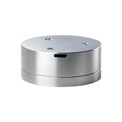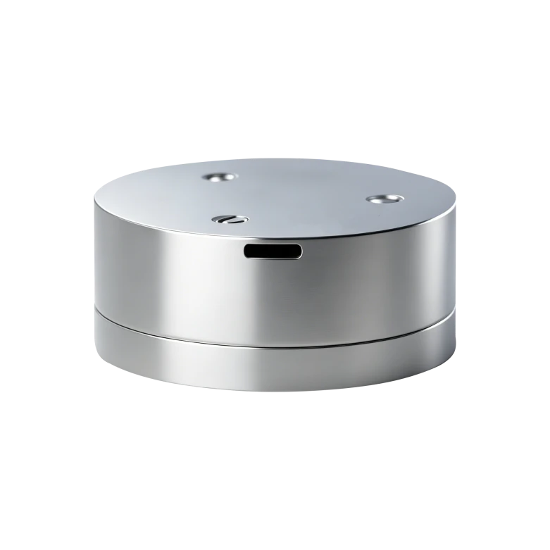
FS40H1 Single-Axis Medium-High Precision Silicon Photonic Gyroscope
Miniature Compact Design
All-Solid-State Design
Strong Environmental Adaptability
Description
Main Features
- Miniature Compact Design
- All-Solid-State Design
- Strong Environmental Adaptability
- High Reliability, Ultra-Long Lifetime
- Fully DigitalRS-422 Electrical Interface Output
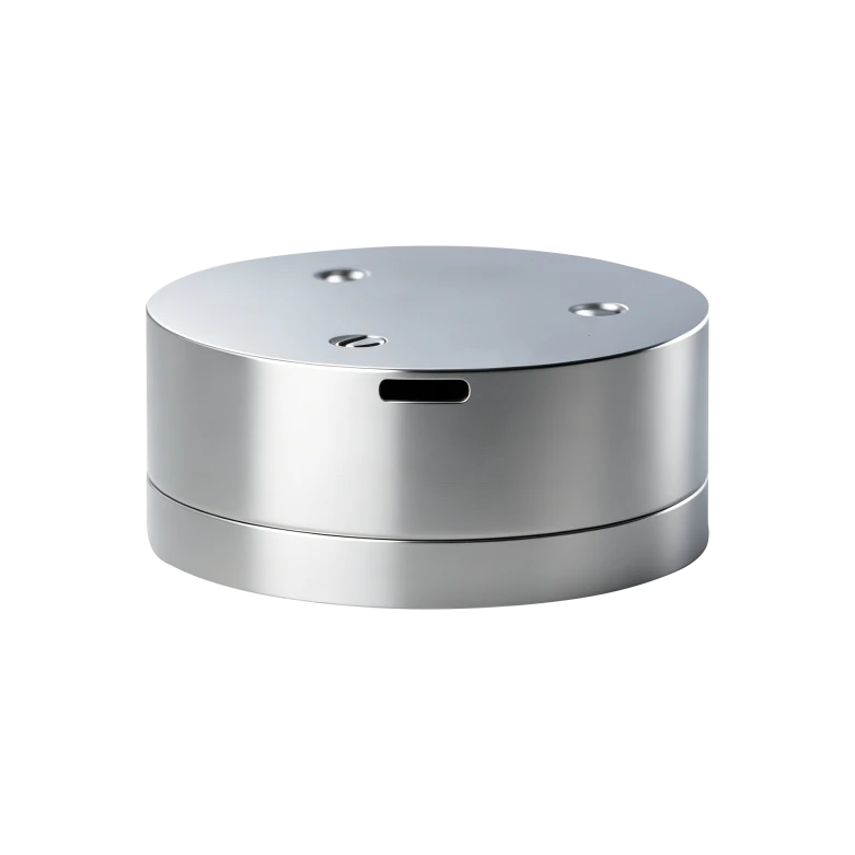
Application Fields
- EO Pod
- Flight Control Platform
- Optical/Photography Platform
- Platform Stabilization Device
- SatCom-on-the-Move
- Inertial Measurement Unit
- Lightweight UAV
Product Introduction
The FS40H1 silicon photonic gyroscope (SPG) breaks through traditional FOG design with a silicon photonic integrated optical circuit. It is an ideal medium-low precision angular rate sensor for navigation and control, widely used in inertial measurement applications. Based on proven designs with engineering optimizations for mass production, it delivers exceptional cost performance. Featuring compact size, light weight, low power consumption, simple interface, and easy operation, it is an ideal angular rate sensor for control fields, widely applied in various inertial measurement and control areas.
Unique Technology
Company is a high-tech enterprise with full closed-loop capabilities from fiber winding equipment and coils to FOGs, fiber/MEMS inertial products, IMU circuits, software, and test equipment. End-to-end process control improves quality and reduces costs. Operating under ISO9001 with strict processes, it ensures product reliability and consistency.
FS40H1 Single-Axis Medium-High Precision Silicon Photonic Gyroscope
FS40H1 Single-Axis Silicon Photonic Gyroscope Performance Parameters
|
Parameter |
A |
B |
|
|
Bias Stability (°/h,1σ,10s) |
≤0.5 |
≤0.3 |
2h Continuous Test,10s avg. Results. |
|
Bias Repeatability (°/h,1σ) |
≤0.5 |
≤0.3 |
Calculation Results from 6 Test Runs |
|
Angle Random Walk (°/√h) |
≤0.05 |
≤0.03 |
|
|
Scale Factor Nonlinearity (ppm) |
≤50 |
≤50 |
Room Temperature |
|
Scale Factor Asymmetry (ppm) |
≤50 |
≤50 |
Room Temperature |
|
Scale Factor Repeatability (ppm) |
≤50 |
≤50 |
Room Temperature |
|
Dynamic Range (°/s) |
±500 |
||
|
Magnetic Sensitivity (°/hr/Gs) |
≤0.05 |
||
|
Bandwidth (Hz) |
>200 |
||
|
Power Consumption (W,Room Temp.) |
<2 |
||
|
Operating Temperature (℃) |
-40 ~ +65 |
||
|
Storage Temperature (℃) |
-50 ~ +70 |
||
|
Vibration Conditions (g, Hz) |
4.2, 20 ~ 2000 |
||
|
Weight (g) |
65±5 |
||
|
Dimensions (mm) |
40*40*17 |
||
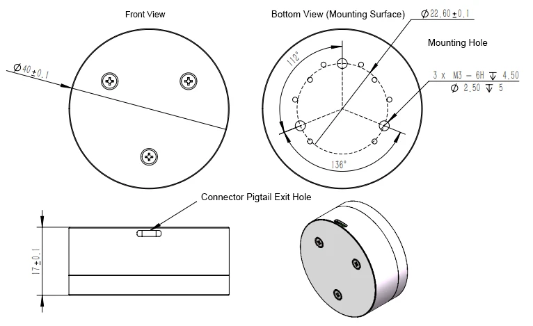
Dimensional Drawing
Introduction
As a new type of fully solid-state gyroscope, the fiber optic gyroscope features fast start-up, wide measurement range, and high reliability. The FS40H1 medium-to-low precision FOG is applicable to land positioning and orientation, vehicle-mounted north seekers, airborne attitude and heading reference systems (AHRS), marine gyrocompasses, and other medium-to-high precision inertial navigation system (INS) applications.
1.1 Scope of Application
This manual applies exclusively to the FS40H1 product and includes performance specifications, technical conditions, outline dimensions, and installation and usage instructions. The technical conditions cover the product's environmental range, electrical performance, and physical characteristics.
1.2 Main Parameters
1.2.1 Main FOG Performance Specifications:
Table 1 Main Product Performance Specifications
|
Parameter |
A |
B |
|
|
Bias Stability (°/h,1σ,10s) |
≤0.5 |
≤0.3 |
2h Continuous Test,10s avg. Results. |
|
Bias Repeatability (°/h,1σ) |
≤0.5 |
≤0.3 |
Calculation Results from 6 Test Runs |
|
Angle Random Walk (°/√h) |
≤0.05 |
≤0.03 |
|
|
Scale Factor Nonlinearity (ppm) |
≤50 |
≤50 |
Room Temperature |
|
Scale Factor Asymmetry (ppm) |
≤50 |
≤50 |
Room Temperature |
|
Scale Factor Repeatability (ppm) |
≤50 |
≤50 |
Room Temperature |
|
Dynamic Range (°/s) |
±500 |
||
|
Magnetic Sensitivity (°/hr/Gs) |
≤0.05 |
||
|
Bandwidth (Hz) |
>200 |
||
|
Power Consumption (W,Room Temp.) |
<2 |
||
|
Operating Temperature (℃) |
-40 ~ +65 |
||
|
Storage Temperature (℃) |
-50 ~ +70 |
||
|
Vibration Conditions (g, Hz) |
4.2, 20 ~ 2000 |
||
|
Weight (g) |
65±5 |
||
|
Dimensions (mm) |
40*40*17 |
||
1.2.2 Mechanical Testing
1.2.2.1 Sine Sweep Vibration
The FOG is mounted on a vibration table via a fixture according to the vibration direction. Sine sweeps are performed in three directions, corresponding to the X, Y, and Z axes respectively. Vibration procedure: energize the vibration table, power on the FOG, and after a preheating period (FOG start-up time), measure the FOG output for approximately 5 min; then perform sine vibration. Vibration conditions: 20 Hz–2000 Hz, sweep duration 5 min, amplitude 4.2 g. Record the FOG output during the vibration process.
Random Vibration
Vibration frequency: 20 Hz–2000 Hz
Vibration duration: 5 min per axis
Vibration direction: X, Y, Z axes
Vibration spectrum: see Figure 1

Figure 1 Vibration Spectrum
Specification requirements:
The FOG shall exhibit no resonance during sine sweep from 20 Hz to 2,000 Hz;
Random vibration: the absolute value of the difference between the bias during vibration and the average of pre- and post-vibration bias shall be less than 0.5 °/h.
1.2.2.2 Mechanical shock shall comply with the requirements of Table 2.
Table 2 Shock Test Conditions
|
Peak Acceleration (g) |
30 |
|
Duration (ms) |
10 |
|
Number of Shocks |
3 shocks per direction |
|
Waveform |
Half-Sine Wave |
|
Direction |
X, Y, Z |
|
Note: The interval between two consecutive shocks shall not be less than 1.5 s. |
|
During the shock test, the product shall remain powered on. After completion of mechanical shock, the product shall operate normally, and the bias change before and after shock shall be less than 1 °/h.
2 Communication Protocol
2.1 RS-422 Mode (Bidirectional)
Bidirectional serial communication, compliant with the RS-422 interface standard;
External trigger signal: 1,000 Hz square wave;
Data transmission begins after the FOG detects the falling edge of the external trigger signal;
Gyro valid data: 32 bits;
Temperature valid data: 14 bits;
Data transmission baud rate: 460.8 kbps;
Data format:
Data transmission format: each data frame consists of 11 bits - Bit 1: Start bit (0); Bits 2–9: Data bits; Bit 10: Even parity bit; Bit 11: Stop bit;
Parity mode: Even parity;
Gyro valid data: 32 bits (MSB is the sign bit, 0 = "+", 1 = "-"); Temperature valid data: 14 bits (MSB is the sign bit, 0 = "+", 1 = "-");
Data packet format: each transmission consists of 10 bytes. Byte 1: Frame header (80H); Byte 2: Gyro data byte 1 (low byte); Byte 3: Gyro data byte 2; Byte 4: Gyro data byte 3; Byte 5: Gyro data byte 4; Byte 6: Gyro data byte 5 (high byte); Byte 7: Check byte, XOR value of the first 5 bytes (gyro data) in the packet; Byte 8: Temperature data low byte; Byte 9: Temperature data high byte; Byte 10: Check byte, XOR value of the first 8 bytes in the packet;
Data storage method.
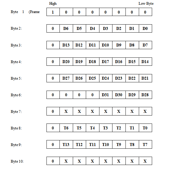
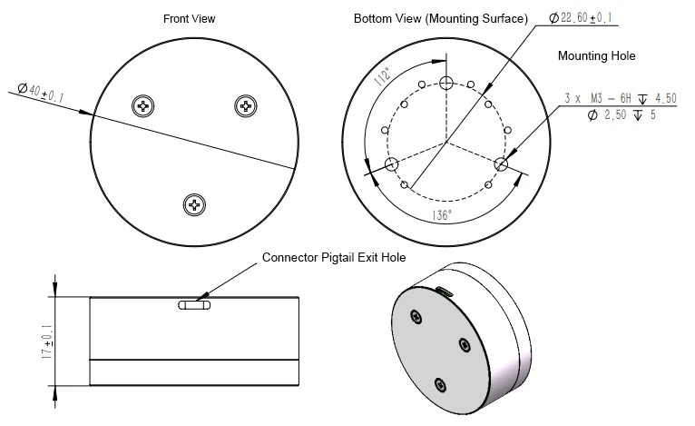
Figure 2 FS40H1 Outline Dimension Drawing
The FOG is equipped with an external J63A-212-009-161JC connector. The pin definitions are provided in Table 1.
Table 1 Gyro Output Connector Electrical Characteristics
|
Pin No. |
Pin Definition |
Marking |
Remarks |
|
1 |
Serial Port T+ |
TX+ |
|
|
2 |
Serial Port T- |
TX- |
|
|
3 |
Serial Port R+ |
RX+ |
RS-422 RX+, Trigger Signal + |
|
4 |
Serial Port R- |
RX- |
RS-422 RX-, Trigger Signal - |
|
6, 7 |
Power +5 V |
+5V |
|
|
8, 9 |
Power Ground |
GND |
Hot Tags: fs40h1 single-axis medium-high precision silicon photonic gyroscope, China fs40h1 single-axis medium-high precision silicon photonic gyroscope manufacturers, factory