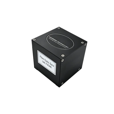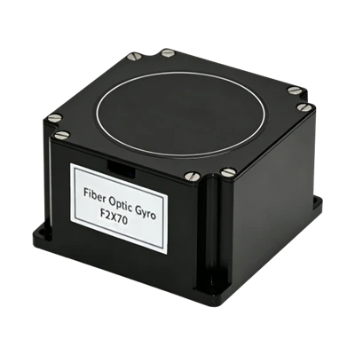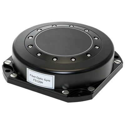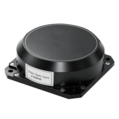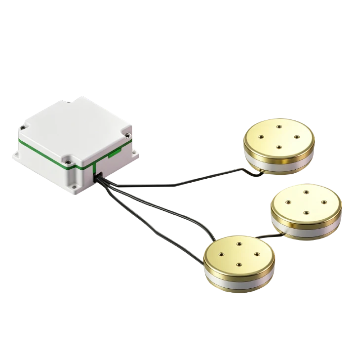
F3G90 Three-Axis FOG
Strong Environmental Adaptability
High Reliability, Ultra-Long Lifetime
Fully DigitalRS-422 Electrical Interface Output
Description
Main Features
- Miniature Compact Design
- All-Solid-State Design
- Strong Environmental Adaptability
- High Reliability, Ultra-Long Lifetime
- Fully DigitalRS-422 Electrical Interface Output
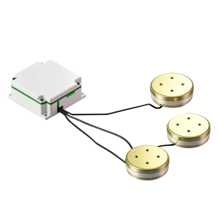
Application Fields
- EO Pod
- Flight Control Platform
- Optical/Photography Platform
- Platform Stabilization Device
- SatCom-on-the-Move
- Inertial Measurement Unit
- Lightweight UAV
Product Overview
The F3G90 miniaturized FOG breaks through traditional design with integrated circuit and optical path. It is an ideal high-precision angular rate sensor for inertial measurement and control. As a fully solid-state gyroscope, it features fast start-up, wide range, and high reliability. The F3G90 three-axis FOG assembly adopts three-axis sharing and split design for low cost and stable performance. With integrated optical-electrical packaging, it is simple to install, suitable for navigation guidance, attitude measurement, and control in small missiles and guided bombs.
Unique Technology
Company is a high-tech enterprise with full closed-loop capabilities from fiber winding equipment and coil winding to IMU circuits, software, and test equipment. End-to-end process control improves quality and reduces costs. Operating under ISO9001 with strict processes, it ensures product reliability and consistency. The flight control system is one of the most critical UAV components, and stable attitude control is essential for mission success. The F3G90 three-axis gyroscope measures pitch, roll, and yaw angular rates during flight, computing angular changes through rate integration.
F3G90 Three-Axis FOG
F3G90 Three-Axis FOG Performance Parameters
|
Parameter |
A |
B |
C |
|
Start-up Time(s) |
5 |
5 |
5 |
|
Null Offset(°/h) |
≤0.3 |
≤0.3 |
≤0.3 |
|
Constant Temp. Bias Stability(10s avg. ,°/h) |
≤0.015 |
≤0.01 |
≤0.006 |
|
Constant Temp. Bias Stability(100s avg. ,°/h) |
≤0.008 |
≤0.005 |
≤0.003 |
|
Variable Temp. Bias Stability(100s avg. ,1℃/min,°/h) |
≤0.06 |
≤0.05 |
≤0.04 |
|
Bias Repeatability(°/h) |
≤0.003 |
≤0.003 |
≤0.003 |
|
Angle Random Walk(°/h1/2) |
≤0.002 |
≤0.001 |
≤0.0005 |
|
Bias Magnetic Sensitivity(°/h/Gs) |
≤0.005 |
||
|
Scale Factor Nonlinearity(ppm) |
≤10 |
||
|
Scale Factor Asymmetry(ppm) |
≤10 |
||
|
Scale Factor Repeatability(ppm) |
≤10 |
||
|
Threshold(°/h) |
≤0.01 |
||
|
Resolution(°/h) |
≤0.01 |
||
|
Bandwidth(Hz) |
≥200 |
||
|
Operating Temperature(℃) |
-45~+65 |
||
|
Storage Temperature(℃) |
-55~+80 |
||
|
Dynamic Range(°/s) |
±300 |
||
|
Supply Voltage(V) |
±5 |
||
|
Steady-State Power Consumption(W) |
≤5.5 |
||
|
Full-Temp. Steady-State Power Consumption(W) |
≤10 |
||
|
Start-up Inrush Current(A) |
<2 |
||
|
Dimensions (mm) |
(Electronic Box)60×60×28/(Sensor Head)Φ90×25 |
||
|
Weight (g) |
<1300 |
||
Dimensional Drawing
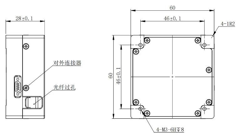
Electronic Box Section
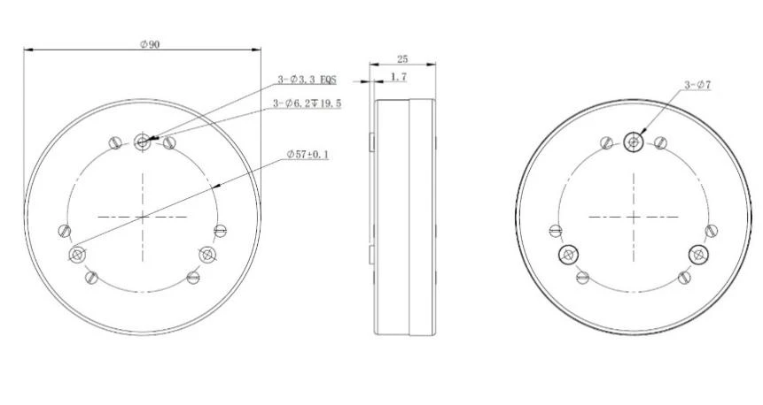
Sensor Head Section
Introduction
Fiber optic gyro, as a new type of all-solid-state gyro, has the advantages of quick startup, wide measurement range and high reliability. Among them, LKF-F3G90 fiber optic gyro inertial combination is for the demand of medium and high precision application background, adopting three-axis common technology, as well as split design, low cost, stable performance; structure adopts the optical circuit and circuit integrated package, simple structure, easy to install, and it can be applied to small missiles and guided bombs in the navigation and guidance, attitude measurement and control systems.
1.1 Application
This manual is only applicable to LKF-F3G90 type products and contains performance index, technical conditions, external dimensions and installation and use. Among them, the technical conditions include the product's environmental range, electrical performance, and physical characteristics.
1.2 Main parameters
1.2.1 The main performance index of fiber optic gyroscope:
Table 1 Product main performance index
|
No. |
Test items |
Unit |
Technical Requirement |
||
|
Selectable Accuracy Levels |
A |
B |
C |
||
|
1 |
Activation Time |
s |
5 |
5 |
5 |
|
2 |
Zero Position |
(°)/h |
≤0.3 |
≤0.3 |
≤0.3 |
|
3 |
Bias Stability at Constant Temperature |
(°)/h |
≤0.015 (10s smoothing) ≤0.008 (100s smoothing) |
≤0.01 (10s smoothing) ≤0.005 (100s smoothing) |
≤0.005 (10s smoothing) ≤0.003 (100s smoothing) |
|
4 |
Bias Stability at Variable Temperature (1°C/Min, 100s Smoothing) |
(°)/h |
≤0.06 |
≤0.05 |
≤0.04 |
|
5 |
Bias Repeatability |
(°)/h |
≤0.003 |
≤0.003 |
≤0.003 |
|
6 |
Random Walk Factor |
(º) /h1/2 |
≤0.002 |
≤0.001 |
≤0.0005 |
|
7 |
Bias Magnetic Sensitivity |
(°)/h/Gs |
≤0.005 |
||
|
8 |
Scale Factor Nonlinearity |
ppm |
≤10 |
||
|
9 |
Scale Factor Asymmetry |
ppm |
≤10 |
||
|
10 |
Scale Factor Repeatability |
ppm |
≤10 |
||
|
11 |
Thresholds |
(°)/h |
≤0.01 |
||
|
12 |
Resolution |
(°)/h |
≤0.01 |
||
|
13 |
Bandwidths |
Hz |
≥200 |
||
|
14 |
Operating Temperature |
℃ |
-45 to +65 |
||
|
15 |
Storage Temperature |
℃ |
-55 to +80 |
||
|
16 |
Dynamic Range |
(°)/s |
±300 |
||
|
17 |
Voltage |
V |
±5 |
||
|
18 |
Steady-State Power |
W |
≤5.5 |
||
|
19 |
Full Temperature Steady State Power |
W |
≤10 |
||
|
20 |
Starting Instantaneous Current |
A |
<2 |
||
|
21 |
Product Weight |
g |
<1300 |
||
2 Communication Protocol
2.1 Fiber Optic Gyro Communication Protocol
2.1.1 Communication formats
Asynchronous serial standard full duplex RS-422 electrical interface standard, communication baud rate 921.600kbit ± 5kbit.
Each byte has 11 bits of data, the low bit is sent first followed by the high bit in the following order: bit 1 is the start bit (0), bits 2 to 9 are data bits, bit 10 is the even parity bit, and bit 11 is the stop bit (1).
2.1.2 Communication Rules
The synchronization signal is a square wave signal (the level form conforms to RS-422 differential signal standard), and the falling edge of the synchronization signal is valid. The gyro starts to send data frame at the falling edge of the synchronization, and the frequency of the data frame is 100Hz~2000Hz (the actual sending frequency is the same as the synchronization signal frequency).
2.1.3 Data frame format
Format of gyro response data to the system.
Gyro transmit data 17 bytes per frame, each byte specific meaning is as follows:
Byte 1 is the frame header: 80H.
The 2nd to 5th bytes are gyro X-axis angle incremental data; the 6th to 9th bytes are gyro Y-axis angle incremental data; the 10th to 13th bytes are gyro Z-axis angle incremental data. Gyro valid data for 28 bits, high bytes in the front, low bytes in the back, the highest bit of each byte is 0, the lower seven bits are valid. The system needs to gyro each axis of the four bytes of data in the lower seven bits spliced into 28-bit signed integer data (complementary code), the highest bit (27th) for the sign bit, the assignment to the 32-bit shaping data needs to be the high four bits filled with sign bits (see Appendix 1).
Bytes 14 through 15 are temperature data. The temperature valid data is 14 bits, with the high byte at the front and the low byte at the back, the highest bit of each byte is 0, and the lower 7 bits are valid. The system needs to splice the lower 7 bits of the two bytes of temperature data into 14 bits of signed plastic data (complement), with the highest bit (13th bit) as the sign bit, and the higher 2 bits need to be filled with sign bits when assigning to the 16-bit plastic data.
The 16th byte is the gyro self-test signal, 8 bits in total, the highest bit is 0.
The 17th byte is the frame checksum byte, and the 2nd to 16th bytes of each frame data are summed to take the lower 7 bits and the highest bit is 0.
Appendix 1:
Gyro data storage method:
The following byte valid bytes are all 7 bits and the highest bit is fixed to 0.
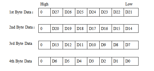
A.5 Calibration
The fiber optic gyro information bytes are summed taking the lower 7 bits of the lower byte and the highest bit is 0.
Note: Fiber optic gyro output valid data (bit27~bit0) for the 28-bit integer complementary code, fiber optic gyro to the system to send, it will be divided into 4 bytes to send the first high byte and then send the low byte, each byte of the low 7-bit valid highest bit is fixed to 0. The system receives the 4 bytes of data to be re-spliced into the IEEE32-bit signed integer number. The transmitted data is the angular velocity output of the fiber optic gyro, with a basic update rate of 2000Hz maximum.
Wiring Definitions
The connector that connects the product to the outside is J30JZLN9ZKCA000, as defined in Table 3.
|
Pin |
Pin Definition |
Color |
Remarks |
|
1, 6 |
Power +5V |
Red |
Power Input |
|
2, 7 |
GND |
Black |
|
|
3 |
Power -5V |
White |
|
|
5 |
Serial Port: Transmit+ |
Yellow |
|
|
9 |
Serial Port: Transmit - |
Orange |
|
|
4 |
Serial Port: Receive+ |
Blue |
|
|
8 |
Serial Port: Receive - |
Green |
Table 3 J30JZLN9ZKCA000 Gyro Connector and Test Line Point Definitions
4,Product Dimension
Overall dimensions
Circuit box external dimensions (mm): 60±0.1×60±0.1×28.0±0.1 (L×W×H);
External dimensions of sensing head (mm): Φ90±0.1×25±0.1;
Mounting Dimensions
Circuit box mounting dimensions (mm): 46±0.1×46±0.1(L×W),M3×4;
Installation size of sensing head (mm): Φ57±0.1,Φ3.3×3;
As shown in
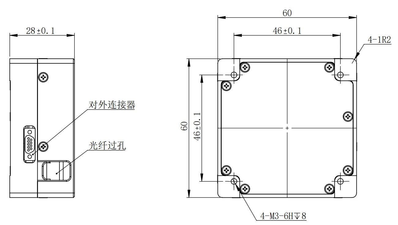
(a).Circuit box section
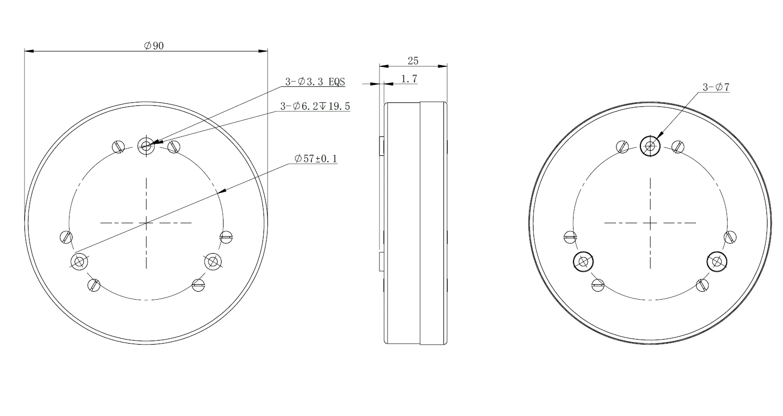
(b) Sensor head section
LKF-F3G90 fiber optic gyroscope shape and installation figure
Hot Tags: f3g90 three-axis fog, China f3g90 three-axis fog manufacturers, factory