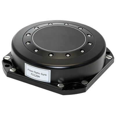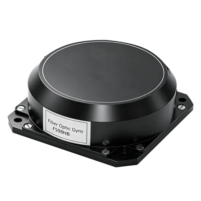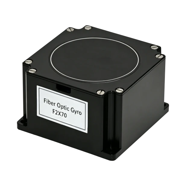
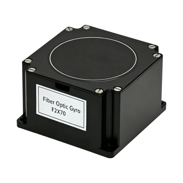
F2X70 Dual-Axis Medium Precision FOG
Strong Environmental Adaptability
High Reliability, Ultra-Long Lifetime
Fully DigitalRS-422 Electrical Interface Output
Description
Main Features
- Miniature Compact Design
- All-Solid-State Design
- Strong Environmental Adaptability
- High Reliability, Ultra-Long Lifetime
- Fully DigitalRS-422 Electrical Interface Output
Application Fields
- EO Pod
- Flight Control Platform
- Optical/Photography Platform
- Platform Stabilization Device
- SatCom-on-the-Move
- Inertial Measurement Unit
- Lightweight UAV
Product Overview
The F2X70 is a miniaturized fiber optic gyroscope with integrated circuitry and optical paths that break from traditional designs. It serves as an ideal high-precision angular rate sensor for control applications and is widely used in inertial measurement. Built on proven designs with engineering optimizations for mass production, it delivers exceptional cost performance. Featuring compact size, light weight, low power consumption, and a simple interface, the F2X70 is the top choice for navigation and control fields.
Unique Technology
Company is a high-tech enterprise with full closed-loop capabilities from fiber winding equipment and coils to FOGs, fiber/MEMS inertial products, IMU circuits, software, and test equipment. End-to-end process control improves quality and reduces costs. Operating under ISO9001, it ensures product reliability and consistency. The F2X70 dual-axis FOG is used in geodetic surveying, mineral/oil exploration, oil drilling guidance, and tunnel construction for positioning and path measurement, as well as dam inclination measurement.
F2X70 Dual-Axis Medium Precision FOG
F2X70 Dual-Axis FOG Performance Parameters
|
Parameter |
A |
Remarks |
|
Bias Stability (°/hr,1σ,10s) |
≤0.20 |
2h Continuous Test,10s avg. Result. |
|
Stabilization Time (s) |
<100 |
|
|
Bias Repeatability (°/hr,1σ) |
≤0.2 |
3 Test Runs Calculation Result. |
|
Resolution (°/hr,1σ ) |
≤0.2 |
|
|
Angle Random Walk (°/√hr) |
≤0.02 |
|
|
Full-Temp Bias Stability (°/hr) |
≤0.5 |
|
|
Scale Factor Nonlinearity (ppm) |
≤20 |
Room Temperature |
|
Scale Factor Repeatability (ppm) |
≤50 |
Room Temperature |
|
Dynamic Range (°/s) |
±400 |
|
|
Bandwidth (Hz) |
≥500 |
|
|
Operating Temperature (℃) |
-40~+65 |
|
|
Storage Temperature (℃) |
-50~+70 |
|
|
Vibration Condition (g, Hz) |
4.2, 20~2000 |
|
|
Weight (g) |
300±50 |
|
|
Dimensions (mm) |
64*60*42 |
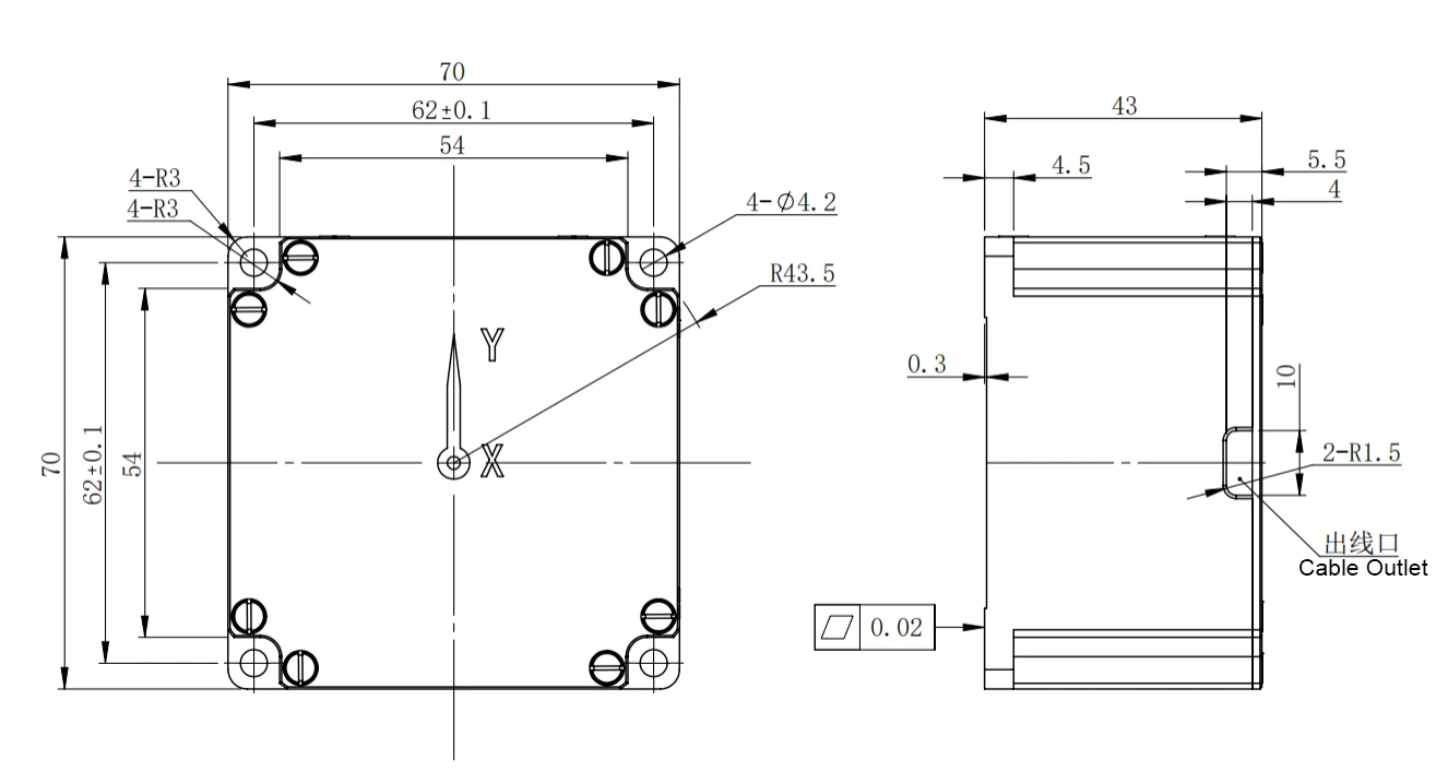
Dimensional Drawing
Introduction
As a new type of all-solid-state gyro, fiber optic gyroscope has the advantages of fast startup, wide measurement range and high reliability, etc. F2X70 dual-axis medium-precision fiber optic gyro can be applied to can be applied to vehicle-mounted stabilized platforms, guide heads, sling bins, etc.
1.1 Application
This instruction manual only applies to F2X70 type products, which contains performance Index, technical conditions, external dimensions and installation and use. Among them, the technical conditions include the product's environmental range, electrical performance, and physical characteristics.
1.2 Main Parameters
1.2.1 Main Parameters:
Table 1 Product main performance index
|
Bias Stability °/hr (1σ,10s) |
≤0.20 |
2h continuous testing, 10s smoothing results |
|
Stabilization Time s |
<100 |
|
|
Bias Repeatability °/hr (1σ) |
≤0.2 |
Calculated results of 3 test data |
|
Resolution °/hr (1σ) |
≤0.2 |
|
|
Random Walk Factor °/√hr |
≤0.02 |
|
|
Bias Repeatability at Full Temperature °/hr |
≤0.5 |
|
|
Scale Factor Nonlinearity (ppm) |
≤20 |
Room temperature |
|
Scale Factor Repeatability (ppm) |
≤50 |
Room temperature |
|
Dynamic Range °/s |
±400 |
|
|
Bandwidth Hz |
≥500 |
|
|
Operating Temperature ℃ |
-40~+65 |
|
|
Storage Temperature ℃ |
-50~+70 |
|
|
Vibration Condition g, Hz |
4.2,20~2000 |
1.2.2 Mechanical Testing
1.2.2.1 Sinusoidal Sweeping Vibration
The gyro is fixed on the vibration table through the fixture according to the direction of vibration, and the gyroscope carries out sinusoidal scanning in 3 directions, corresponding to the X-axis, Y-axis, and Z-axis directions, respectively. Vibration steps; vibration table plus excitation, to the gyroscope power, after a certain period of warm-up (gyro start-up time), test the output value of the gyroscope, about 5min; sinusoidal vibration. Vibration conditions: 20Hz-2000Hz, scanning time 5min, amplitude 4.2g. vibration process, record the gyroscope output.
Random Vibration
Vibration Frequency: 20Hz~2000Hz
Vibration Time: 5min for each axis
Vibration Direction: X, Y, Z axis
Vibration Spectrum: see Figure 1

Index requirements:
Fiber optic gyro shall be no resonance with sinusoidal scanning in the range of 20 HZ to 2000 Hz;
Random vibration: the absolute value of the bias in the vibration and the average bias before and after the vibration shall be less than 0.2º/h.
1.2.2.2 Mechanical impacts are as required by Table 2.
Table 2 Impact Conditions
|
Peak Acceleration (g) |
30 |
|
Duration (ms) |
10 |
|
Times of Impacts |
3 times in each direction |
|
Waveform |
half-sine wave |
|
Directions |
X, Y, Z |
|
Note: The interval between two impacts is not less than 1.5s. |
Impact process, the product should be able to work normally after mechanical impacts in the state of electricity, the bias should be less than 0.2º/h before and after the impact.
2 Communication Protocol
2.1 RS-422 Method
Baud rate: 460.8K;
Communication frame format
Per frame contains 10 bytes, the first byte is 0x80. Byte 1, 2, 3 are the high, medium and low 8-bit data of the gyro in horizontal direction. Byte 5, 6, 7 are the high, medium and low 8-bit data of the gyro in vertical direction. Byte 8, 9 are for the temperature, Byte 10 is the sum of byte 2-9, takes the lower 8 bits.
The format is shown in Table 3, 11 bits per byte, in the following order: Start from 1 bit
Data bit is 8 bits (send low first, then high), even parity is 1 bit, stop bit is 1 bit
Communication Rule
The gyro starts to send data after it detects falling of the external trigger signal, 2000Hz supported.
Table 3 Format of Each Byte of The Output Data Frame
|
Byte |
Significance |
Bit 7 |
Bit 6 |
Bit 5 |
Bit 4 |
Bit 3 |
Bit 2 |
Bit 1 |
Bit 0 |
|
1 |
Header |
1 |
0 |
0 |
0 |
0 |
0 |
0 |
0 |
|
2 |
Horizontal gyro high 8 bits |
PD23 |
PD22 |
PD21 |
PD20 |
PD19 |
PD18 |
PD17 |
PD16 |
|
3 |
Horizontal gyro medium 8 bits |
PD15 |
PD14 |
PD13 |
PD12 |
PD11 |
PD10 |
PD9 |
PD8 |
|
4 |
Horizontal gyro low 8 bits |
PD7 |
PD6 |
PD5 |
PD4 |
PD3 |
PD2 |
PD1 |
PD0 |
|
5 |
Vertical gyro high 8 bits |
CD23 |
CD22 |
CD21 |
CD20 |
CD19 |
CD18 |
CD17 |
CD16 |
|
6 |
Vertical gyro medium 8 bits |
CD15 |
CD14 |
CD13 |
CD12 |
CD11 |
CD10 |
CD9 |
CD8 |
|
7 |
Vertical gyro low 8 bits |
CD7 |
CD6 |
CD5 |
CD4 |
CD3 |
CD2 |
CD1 |
CD0 |
|
8 |
Temperature |
X |
X |
T13 |
T12 |
T11 |
T10 |
T9 |
T8 |
|
9 |
Temperature |
T7 |
T6 |
T5 |
T4 |
T3 |
T2 |
T1 |
T0 |
|
10 |
Verification frame |
Sum of byte 2 to 9 take the lower 8 bits. |
|||||||
3 Connection Definition
The gyroscope electrical interface uses a J30-15ZK connector, defined in Table 4.
|
Number |
Definition |
Mark |
Color |
|
1 |
Serial T+ |
TX+ |
Yellow |
|
2 |
Serial T- |
TX- |
Orange |
|
3 |
Serial port R+ |
RX+ |
Blue |
|
4 |
Serial port R- |
RX- |
Green |
|
5, 13 |
Power supply +5V |
+5V |
Red |
|
6, 7 |
POWER GROUND |
GND |
Black |
4 Dimensions
Horizontal dual-axis fiber-optic gyroscope external dimensions: 70mm × 70mm × 43mm, mounting dimensions: four holes 62mm × 62 mm, mounting screws: 4 M3 screws, the shape and mounting dimensions shown in Figure 2.
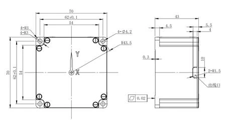
Fig. 2 F2X70 Dimension
Hot Tags: f2x70 dual-axis medium precision fog, China f2x70 dual-axis medium precision fog manufacturers, factory