F3G80 Three-Axis FOG
Strong Environmental Adaptability
High Reliability, Ultra-Long Lifetime
Fully DigitalRS-422 Electrical Interface Output
Description
Main Features
- Miniature Compact Design
- All-Solid-State Design
- Strong Environmental Adaptability
- High Reliability, Ultra-Long Lifetime
- Fully DigitalRS-422 Electrical Interface Output
Application Fields
- EO Pod
- Flight Control Platform
- Optical/Photography Platform
- Platform Stabilization Device
- SatCom-on-the-Move
- Inertial Measurement Unit
- Lightweight UAV
Product Overview
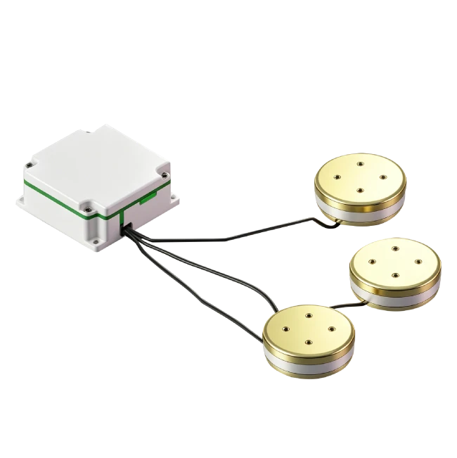
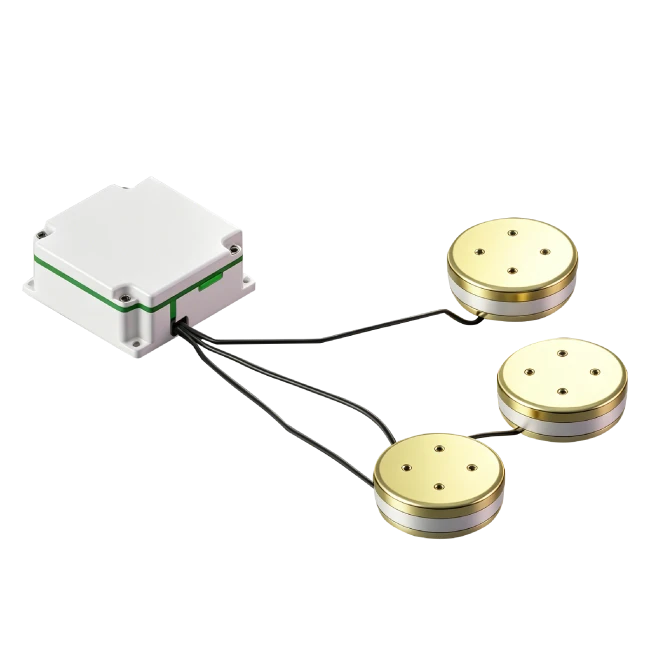
The F3G80 miniaturized FOG breaks through traditional design with integrated circuit and optical path. It is an ideal high-precision angular rate sensor for inertial measurement and control. As a fully solid-state gyroscope, it features fast start-up, wide range, and high reliability. The F3G80 three-axis FOG assembly adopts three-axis sharing and split design for low cost and stable performance. With integrated optical-electrical packaging, it is simple to install, suitable for navigation guidance, attitude measurement, and control in small missiles and guided bombs.
Unique Technology
Company is a high-tech enterprise with full closed-loop capabilities from fiber winding equipment and coil winding to IMU circuits, software, and test equipment. End-to-end process control improves quality and reduces costs. Operating under ISO9001 with strict processes, it ensures product reliability and consistency. When GPS signals are poor, the F3G80 continues precise navigation using known heading, orientation, and velocity-the basic principle of inertial navigation-while also correcting excessive positioning deviations during GPS outages.
F3G80 Three-Axis FOG
F3G80 Three-Axis FOG Performance Parameters
|
Parameter |
A |
B |
C |
|
Start-up Time(s) |
5 |
5 |
5 |
|
Null Offset(°/h) |
≤0.3 |
≤0.3 |
≤0.3 |
|
Constant Temp. Bias Stability(10s avg. ,°/h) |
≤0.020 |
≤0.015 |
≤0.01 |
|
Constant Temp. Bias Stability(100s avg. ,°/h) |
≤0.010 |
≤0.008 |
≤0.005 |
|
Variable Temp. Bias Stability(100s avg. ,1℃/min,°/h) |
≤0.08 |
≤0.06 |
≤0.05 |
|
Bias Repeatability(°/h) |
≤0.020 |
≤0.015 |
≤0.010 |
|
Angle Random Walk(°/√h) |
≤0.002 |
≤0.002 |
≤0.001 |
|
Bias Magnetic Sensitivity(°/h/Gs) |
≤0.005 |
||
|
Scale Factor Nonlinearity(ppm) |
≤20 |
||
|
Scale Factor Asymmetry(ppm) |
≤20 |
||
|
Scale Factor Repeatability(ppm) |
≤20 |
||
|
Threshold(°/h) |
≤0.01 |
||
|
Resolution(°/h) |
≤0.01 |
||
|
Bandwidth(Hz) |
≥200 |
||
|
Operating Temperature(℃) |
-45~+65 |
||
|
Storage Temperature(℃) |
-55~+80 |
||
|
Dynamic Range(°/s) |
±300 |
||
|
Supply Voltage(V) |
±5 |
||
|
Steady-State Power Consumption(W) |
≤5.5 |
||
|
Full-Temp. Steady-State Power Consumption(W) |
≤10 |
||
|
Start-up Inrush Current(A) |
<2 |
||
|
Dimensions(mm) |
(Sensor Head)Φ76×18/(Electronic Box)60×60×28 |
||
|
Weight(g) |
<900 |
||
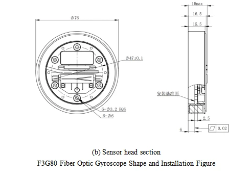
Dimensional Drawing
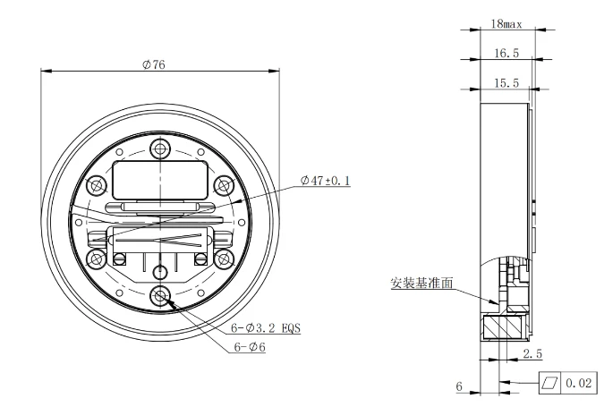
Sensor Head Section
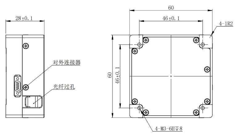
Electronic Box Section
Introduction
Fiber optic gyro, as a new type of all-solid-state gyro, has the advantages of quick startup, wide measurement range and high reliability. Among them, F3G80 fiber optic gyro inertial combination is for the demand of medium and high precision application background, adopting three-axis common technology, as well as split design, low cost, stable performance; structure adopts the optical circuit and circuit integrated package, simple structure, easy to install, and it can be applied to small missiles and guided bombs in the navigation and guidance, attitude measurement and control systems.
1.1 Application
This manual is only applicable to F3G80 type products and contains performance index, technical conditions, external dimensions and installation and use. Among them, the technical conditions include the product's environmental range, electrical performance, and physical characteristics.
1.2 Main parameters
1.2.1 The main performance index of fiber optic gyroscope:
Table 1 Product main performance index
|
No. |
Test items |
Unit |
Technical Requirement |
||
|
Selectable Accuracy Levels |
A |
B |
C |
||
|
1 |
Activation Time |
s |
5 |
5 |
5 |
|
2 |
Zero Position |
(°)/h |
≤0.3 |
≤0.3 |
≤0.3 |
|
3 |
Bias Stability at Constant Temperature |
(°)/h |
≤0.020 (10s smoothing) ≤0.010 (100s smoothing) |
≤0.015 (10s smoothing) ≤0.008 (100s smoothing) |
≤0.01 (10s smoothing) ≤0.005 (100s smoothing) |
|
4 |
Bias Stability at Variable Temperature (1°C/Min, 100s Smoothing) |
(°)/h |
≤0.08 |
≤0.06 |
≤0.05 |
|
5 |
Bias Repeatability |
(°)/h |
≤0.020 |
≤0.015 |
≤0.010 |
|
6 |
Random Walk Factor |
(º) /h1/2 |
≤0.002 |
≤0.002 |
≤0.001 |
|
7 |
Bias Magnetic Sensitivity |
(°)/h/Gs |
≤0.005 |
||
|
8 |
Scale Factor Nonlinearity |
ppm |
≤20 |
||
|
9 |
Scale Factor Asymmetry |
ppm |
≤20 |
||
|
10 |
Scale Factor Repeatability |
ppm |
≤20 |
||
|
11 |
Thresholds |
(°)/h |
≤0.01 |
||
|
12 |
Resolution |
(°)/h |
≤0.01 |
||
|
13 |
Bandwidths |
Hz |
≥200 |
||
|
14 |
Operating Temperature |
℃ |
-45 to +65 |
||
|
15 |
Storage Temperature |
℃ |
-55 to +80 |
||
|
16 |
Dynamic Range |
(°)/s |
±300 |
||
|
17 |
Voltage |
V |
±5 |
||
|
18 |
Steady-State Power |
W |
≤5.5 |
||
|
19 |
Full Temperature Steady State Power |
W |
≤10 |
||
|
20 |
Starting Instantaneous Current |
A |
<2 |
||
|
21 |
Product Weight |
g |
<900 |
||
2 Communication Protocol
2.1 Fiber Optic Gyro Communication Protocol
Interface form: EIA-RS422 compliant;
Baud rate: 921600bps;
Data format: 1 start bit, 8 data bits, 1 stop bit, no parity.
Data update rate: 4kHz
|
No.(Byte) |
Content |
Bytes |
Data Type |
Notes |
|
1 |
frame header |
1 |
UCHAR8 |
OxEB |
|
2 |
frame header |
1 |
UCHAR8 |
0x90 |
|
3 |
frame number |
1 |
UCHAR8 |
frame count |
|
4~6 |
X-axis gyro data |
3 |
INT24 |
|
|
7 |
X temperature |
1 |
CHAR8 |
|
|
8-10 |
Y-axis gyro data |
3 |
INT24 |
|
|
11 |
Y temperature |
1 |
CHAR8 |
|
|
12-14 |
Z-axis gyro data |
3 |
INT24 |
|
|
15 |
Z temperature |
1 |
CHAR8 |
|
|
16 |
checksum |
1 |
UCHAR8 |
check |
Remarks:
Data frames are multibyte data, with the low byte sent first, followed by the high byte;
The effective gyro data is a 32-bit signed integer with the highest bit being the sign bit;
The valid temperature data is 8-bit signed integer, the highest bit is the sign bit, and the temperature scale factor is 1LSB/°C. The check byte is the sum of the data from byte 1 to byte 15, and the lower 8 bits are taken;
Gyro data is in incremental form, i.e., the incremental value of the gyro's angle over the time of the sending cycle.
3 Wiring Definitions
The connector that connects the product to the outside is J30JZLN9ZKCA000, as defined in Table 3.
|
Pin |
Pin Definition |
Color |
Remarks |
|
1, 6 |
Power +5V |
Red |
Power Input |
|
2, 7 |
GND |
Black |
|
|
3 |
Power -5V |
White |
|
|
5 |
Serial Port: Transmit+ |
Yellow |
|
|
9 |
Serial Port: Transmit - |
Orange |
|
|
4 |
Serial Port: Receive+ |
Blue |
|
|
8 |
Serial Port: Receive - |
Green |
Table 3 J30JZLN9ZKCA000 Gyro Connector and Test Line Point Definitions
4 Product Dimension
Overall dimensions
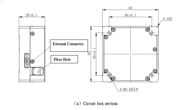
Circuit box external dimensions (mm): 60±0.1×60±0.1×28.0±0.1 (L×W×H);
External dimensions of sensing head (mm): Φ76±0.1×18±0.1;
Mounting Dimensions
Circuit box mounting dimensions (mm): 46±0.1×46±0.1 (L×W), M3×4;
Installation size of sensing head (mm): Φ47±0.1, Φ3.3×6;
As shown in the figure below.
Hot Tags: f3g80 three-axis fog, China f3g80 three-axis fog manufacturers, factory