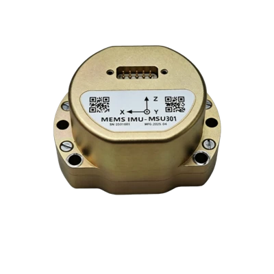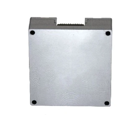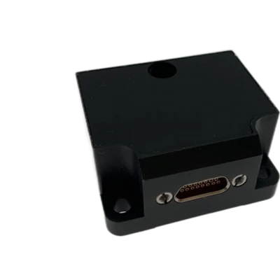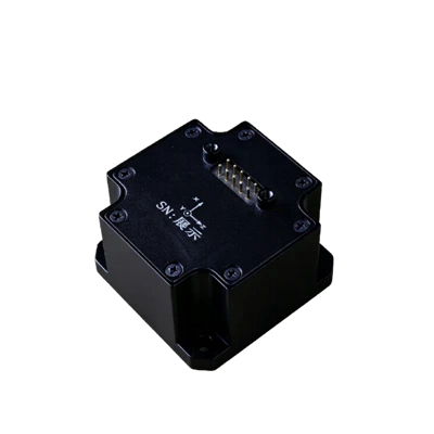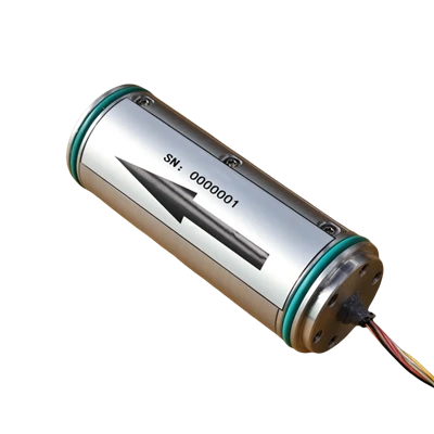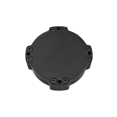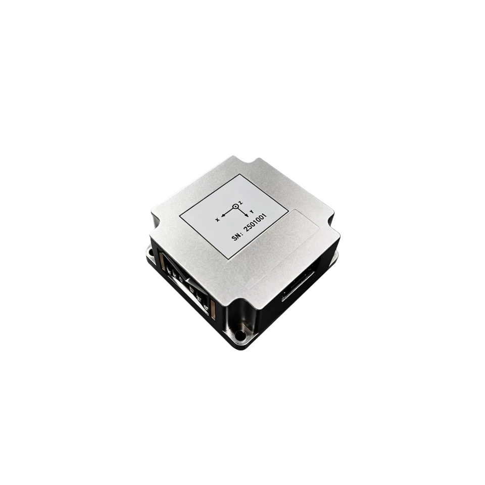
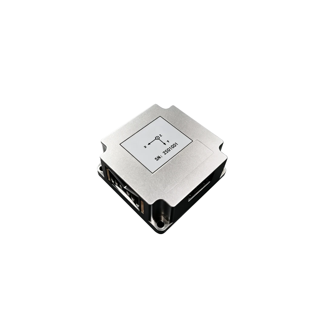
MSU304 High Precision MEMS Inertial Measurement Unit
High precision, high reliability
100% Domestically sourced components
Compact size, low weight
Description
Key Features
- High precision, high reliability
- 100% Domestically sourced components
- Compact size, low weight
- -50℃ to+70℃ full-temp. calibration and compensation
- Resistance to harsh mechanical environment
- Software online upgrade
Applications
- Construction Machinery
- Flight Control
- High-Precision Surveying and Mapping
- Maritime and Offshore Operations
Product Overview
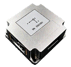
MSU304 MEMS Inertial Measurement Unit is an ultra-high precision, high-reliability 6-axis MEMS Inertial Attitude and Heading Reference System, widely applicable in navigation, control and measurement fields represented by vehicles, ships, and UAVs.
The MSU304 series IMU integrates high-performance MEMS gyroscopes and accelerometers within an independent structure, features system sealing design with internal vibration damping, and meets the requirements of high-precision, high-dynamic navigation applications in harsh environments.
MSU304 MEMS Inertial Measurement Unit
|
Model |
MSU304 A |
MSU304 B |
|
|
MEMS Gyroscope |
|||
|
Range (°/s) |
±300 |
±300 |
|
|
Bias @ Full temp. (°/h, 3σ) |
≤2 |
≤2 |
|
|
Bias Stability(°/h, 10s Smoothing) |
≤0.15 |
≤0.3 |
|
|
Bias Instability(°/h, allan, typ) |
≤0.03 |
≤0.03 |
|
|
Bias Repeatability (°/h, 1σ) |
≤0.15 |
≤0.3 |
|
|
Angle Random Walk (°/√h) |
≤0.005 |
≤0.02 |
|
|
Scale Factor Nonlinearity (ppm) |
≤100 |
≤100 |
|
|
Cross-Axis Coupling (rad) |
≤0.001 |
≤0.001 |
|
|
Bandwidth (Hz) |
≥100 |
≥200 |
|
|
MEMS Accelerometer |
|||
|
Range (g) |
±30 |
±30 |
|
|
Bias @ Full temp. (mg) |
≤0.5 |
≤2 |
|
|
Bias Stability(μg, 10s Smoothing) |
≤10 |
≤50 |
|
|
Bias Instability(μg ,allan, typ) |
≤3 |
≤30 |
|
|
Bias Repeatability (μg) |
≤10 |
≤50 |
|
|
Velocity Random Walk (m/s/√h) |
≤0.01 |
≤0.03 |
|
|
Scale Factor Nonlinearity (ppm, ±1g) |
≤100 |
≤100 |
|
|
Cross-Axis Coupling (rad) |
≤0.001 |
≤0.001 |
|
|
Bandwidth (Hz) |
≥200Hz |
≥200Hz |
|
|
Electrical/Mechanical Interface |
|||
|
Power Supply (V) |
5~12 (Ripple ≤100mV) |
||
|
Steady-State Power(W) |
≤2 |
||
|
Startup Time (s) |
≤2 |
||
|
Communication Interface |
RS-422 |
||
|
Update Rate (Hz, Max) |
2000 |
||
|
Dimensions (mm × mm ×mm) |
70×70×30 |
||
|
Weight (g) |
220±10 |
||
|
Operating Environment |
|||
|
Operating Temperature (℃) |
-50~+80(Or -50 startup, -55 operating) |
||
|
Storage Temperature (℃) |
-55~85 |
||
|
Vibration (g,RMS) |
13 |
||
|
Shock (g) |
1000 |
||
Product Introduction
Product Overview
MSU304 MEMS IMU is an ultra-high precision, highly reliable six-axis MEMS inertial attitude and heading reference system, which can be widely used in navigation, control, and measurement fields represented by vehicles, ships, and UAVs.
MSU304 series IMU integrates high-performance MEMS gyroscope and high-performance accelerometer within an independent structure, featuring sealed design and internal shock absorption treatment, suitable for high-precision, high-dynamic navigation applications in harsh environments.
Key Features
- High precision, high reliability
- 100% Domestically produced components
- Compact size, low weight
- -50°c to +70°c over full temperature range calibration and compensation
- Harsh mechanical environment resistance
- Online firmware update
Applications
- Construction Machinery
- Flight Control
- High-Precision Surveying
- Marine and Offshore Operations
Technical Specifications
Table 1 MSU304 Inertial Measurement Unit Performance Specifications
|
Model |
MSU304 A |
MSU304 B |
|
Gyroscope |
||
|
Range (°/s) |
±300 |
±300 |
|
Bias @ Full temp.(°/h,3σ) |
≤2 |
≤2 |
|
Bias Stability (°/h,10s smoothing) |
≤0.15 |
≤0.3 |
|
Bias Instability (°/h, allan, typ) |
≤0.03 |
≤0.03 |
|
Bias Repeatability (°/h,1σ) |
≤0.15 |
≤0.3 |
|
Angle Random Walk (°/√h) |
≤0.005 |
≤0.02 |
|
Scale Factor Nonlinearity (ppm) |
≤100 |
≤100 |
|
Cross-Axis Coupling (rad) |
≤0.001 |
≤0.001 |
|
Bandwidth (Hz) |
≥100 |
≥200 |
|
Accelerometer |
||
|
Range (g) |
±30 |
±30 |
|
Bias @ Full temp. (mg) |
≤0.5 |
≤2 |
|
Bias Stability (ug,10ssmoothing) |
≤10 |
≤50 |
|
Bias Instability (μg,allan,typ) |
≤3 |
≤30 |
|
Bias Repeatability (ug) |
≤10 |
≤50 |
|
Velocity Random Walk (m/s/√h) |
≤0.01 |
≤0.03 |
|
Scale Factor Nonlinearity (ppm,±1g) |
≤100 |
≤100 |
|
Cross-Axis Coupling (rad) |
≤0.001 |
≤0.001 |
|
Bandwidth (Hz) |
≥200Hz |
≥200Hz |
|
Electrical/Mechanical Interface |
||
|
Power Supply (V) |
5~12(ripple≤100mV) |
|
|
Steady-State Power Consumption(W) |
≤2 |
|
|
Startup Time (s) |
≤2 |
|
|
Communication Interface |
RS-422 |
|
|
Update Rate (Hz, max) |
2000 |
|
|
Dimensions (mm×mm×mm) |
70×70×30 |
|
|
Weight (g) |
220±10 |
|
|
Operating Environment |
||
|
Operating Temperature (°C) |
-50~+80(or-50startup,-55operation) |
|
|
Storage Temperature (°C) |
-55~85 |
|
|
Vibration (g, RMS) |
13 |
|
|
Shock (g) |
1000 |
|
Mechanical Characteristics
MSU304 Inertial Measurement Unit adopts aerospace aluminum alloy structure, which is lightweight with high structural integrity, resistant to vibration and shock. The dimension drawing is shown below:
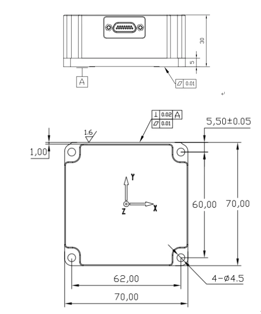
Fig. 1 Mechanical Dimensions
Product Marking and Polarity
Product installation must ensure a fixed relationship between the product body frame and the host vehicle body frame.MSU304 MEMS Inertial Measurement Unit body frame is defined as follows.
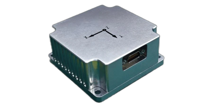
Fig. 2 Product Coordinate System
Interface Definition
MSU304 Inertial Measurement Unit external output usesJ30J-15ZK (mating connector J30J-15TJL ), primarily for power supply and external communication. The connector pin definition is shown in Table 2 .
Table 2 MSU304 IMU Connector Pin Definition
|
Pin No. |
Definition |
Remarks |
|
1 |
RS422 T- |
RS422Interface |
|
2 |
RS422 R- |
|
|
9 |
RS422 T+ |
|
|
10 |
RS422 R+ |
|
|
13 |
RS422 GND |
|
|
8 |
POWER_IN |
5~12VPower Supply |
|
15 |
GND |
|
|
4 |
TOV |
pulse signal,5V TTL level, rising edge active |
|
12 |
TOV GND |
After the power supply voltage drops below the device operating threshold voltage, the power-off hold time before re-powering tOFF must not be less than 3s; insufficient power-off interval may cause device startup abnormality, latch-up, or initialization failure.
External Communication
Baud Rate115200bps,8-bit data,1-bit stop bit, no parity,0xA5data frame, update rate125Hzadjustable.
Gyroscope output is in angular increment format, °/sample, accelerometer output is in velocity increment format , m/s/ sample.
Table 3 IMU Output Data Format
|
No. |
Parameter Name |
Valid Range |
Bytes |
Scale Factor |
Remarks |
|
1 |
Frame Header |
0xA5 |
1 |
- |
Data Packet Header |
|
2 |
X-Axis Angular Increment |
[-400,400] |
3 |
2-21 |
Unit:°, MSB first then LSB, the MSB of the first byte is the sign bit. For detailed algorithm, see Note1. Valid range corresponds to the angular rate range of the respective axis. |
|
3 |
Y-Axis Angular Increment |
[-400,400] |
3 |
2-21 |
|
|
4 |
Z-Axis Angular Increment |
[-400,400] |
3 |
2-21 |
|
|
5 |
Gyroscope Status |
- |
1 |
- |
All0zeros indicates normal; for detailed definition, see Table5-10. |
|
6 |
X-Axis Velocity Increment |
[-10,10] |
3 |
2-22 |
Unit:m/s, MSB first then LSB, the MSB of the first byte is the sign bit. For detailed algorithm, see Note2. Valid range corresponds to the acceleration range of the respective axis. |
|
7 |
Y-Axis Velocity Increment |
[-10,10] |
3 |
2-22 |
|
|
8 |
Z-Axis Velocity Increment |
[-10,10] |
3 |
2-22 |
|
|
9 |
Accelerometer Status |
- |
1 |
- |
All0zeros indicates normal; for detailed definition, see Table5-10. |
|
10 |
X-Axis Gyroscope Temperature |
[-128,128] |
2 |
|
Unit: °C, MSB first then LSB, the MSB of the first byte is the sign bit. For detailed algorithm, see Note3. |
|
11 |
Y-Axis Gyroscope Temperature |
[-128,128] |
2 |
|
Unit: °C, MSB first then LSB, the MSB of the first byte is the sign bit. For detailed algorithm, see Note3. |
|
12 |
Z-Axis Gyroscope Temperature |
[-128,128] |
2 |
|
Unit: °C, MSB first then LSB, the MSB of the first byte is the sign bit. For detailed algorithm, see Note3. |
|
13 |
Gyroscope Thermometer Status |
- |
1 |
- |
All0zeros indicates normal; for detailed definition, see Table5-10. |
|
14 |
X-Axis Accelerometer Temperature |
[-128,128] |
2 |
|
Unit: °C, MSB first then LSB, the MSB of the first byte is the sign bit. For detailed algorithm, see Note3. |
|
15 |
Y-Axis Accelerometer Temperature |
[-128,128] |
2 |
|
Unit: °C, MSB first then LSB, the MSB of the first byte is the sign bit. For detailed algorithm, see Note3. |
|
16 |
Z-Axis Accelerometer Temperature |
[-128,128] |
2 |
|
Unit: °C, MSB first then LSB, the MSB of the first byte is the sign bit. For detailed algorithm, see Note3. |
|
17 |
Accelerometer Thermometer Status |
- |
1 |
- |
All0zeros indicates normal; for detailed definition, see Table5-10. |
|
18 |
Frame Counter |
[0,255] |
1 |
1 |
0–255Sequential Counter |
|
19 |
Time Delay |
2 |
Unit:us, MSB first then LSB, the MSB of the first byte is the sign bit. For detailed algorithm, see Note4. |
||
|
20 |
CRC32 |
- |
4 |
- |
CRC32checksum, see Note5 |
|
21 |
<CR> |
0x0D |
1 |
||
|
22 |
<LF> |
0x0A |
1 |


Notes:
AR1MSB=0, gyroscope angular increment output[°]=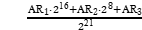 ;
AR1MSB=1, gyroscope angular increment output[°]= ;
Where: is the high 8 bits of the three-byte angular increment output per gyroscope axis;
 is the middle 8 bits of the three-byte angular increment output per gyroscope axis;
 is the low 8 bits of the three-byte angular increment output per gyroscope axis.
AR1MSB=0, velocity increment output[m/s]=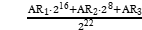 ;
AR1MSB=1, velocity increment output[m/s]= ;
Where: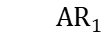 is the high 8 bits of the three-byte velocity increment output per accelerometer axis;
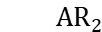 is the middle 8 bits of the three-byte velocity increment output per accelerometer axis;
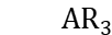 is the low 8 bits of the three-byte velocity increment output per accelerometer axis.
T1MSB=0, temperature output[°C]= ;
T1MSB=1, temperature output[°C]=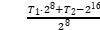 .
Where: is the high 8 bits of the two-byte temperature output per axis;
 is the time delay output per axis[us]=

Where:T1is the high 8 bits of the two-byte time delay output;
T2is the low 8 bits of the two-byte time delay output.
Time delay output[us]= 
Where:T1is the high 8 bits of the two-byte time delay output;
T2is the low 8 bits of the two-byte time delay output.
CRCChecksum Method
CRCuses standardCRC-32polynomial:

Table and lookup function code generated based on this polynomial.
The product features built-in self-test and real-time operating status output. The data frame contains a status byte that outputs real-time product operating status information after power-on startup is complete. The definition of status bits is shown in Table4.
Table 4 Product Status Word Definition
|
Bit |
Definition |
|
7 |
0=Normal,1=Full System Abnormal |
|
6 |
0=Normal,1=Starting Up |
|
5 |
0=Normal,1=External Environment Abnormal |
|
4 |
0=Normal,1=Three-Axis Exceeds Operating Conditions |
|
3 |
0=Normal,1=Three-Axis Output Error |
|
2 |
0=Normal,1=Z-Axis Exceeds Operating Conditions or Error |
|
1 |
0=Normal,1=Y-Axis Exceeds Operating Conditions or Error |
|
0 |
0=Normal,1=X-Axis Exceeds Operating Conditions or Error |
Precautions
- Pay attention to the product electrical interface definition. During use, strictly follow the pin arrangement to avoid incorrect connections;
- The product is a precision measurement device. During handling, avoid shock, collision, and other conditions beyond the product's tolerance range;
- Product installation significantly affects angular rate measurement. To avoid introducing installation errors, the mounting surface must have good flatness;
- To ensure measurement accuracy, the product must be installed securely and firmly to avoid measurement errors caused by looseness;
- During product installation and operation, ESD protection should be observed. It is recommended to wear an ESD wrist strap;
- Please strictly follow the requirements in this manual. Confirm that the external environment matches the usage requirements. If problems occur, do not open the product cover or modify the internal structure. If you have any issues, please contact our technical support personnel promptly.
Hot Tags: msu304 high precision mems inertial measurement unit, China msu304 high precision mems inertial measurement unit manufacturers, factory