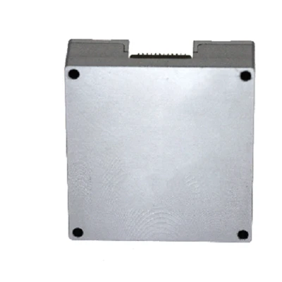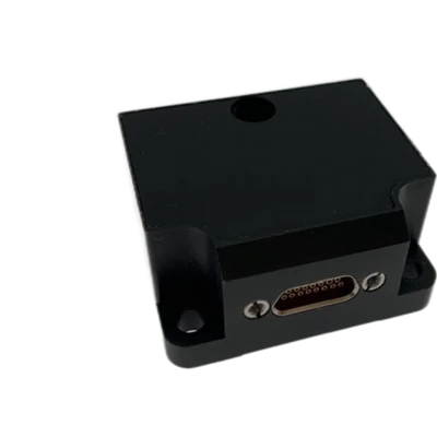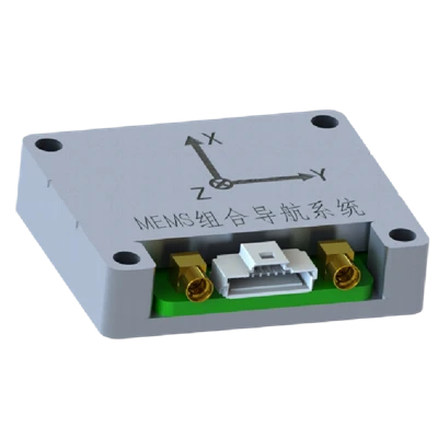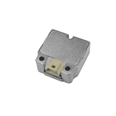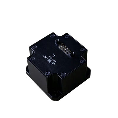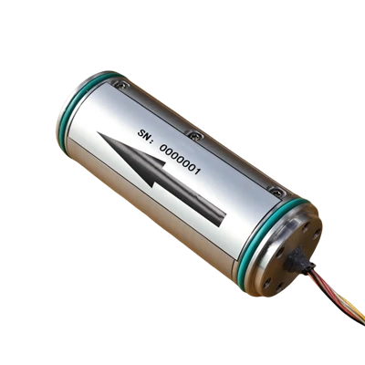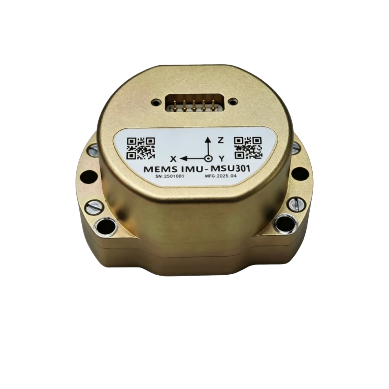
MSU301 MEMS Inertial Measurement Module
Harsh-environment resistant
Online firmware upgrade
Drop-in replacement for HG4930
Description
Key Features
- High performance & reliability
- Full-temp calibration -40 to +80°C
- High-speed gyro sampling & sync
- Harsh-environment resistant
- Online firmware upgrade
- Drop-in replacement for HG4930
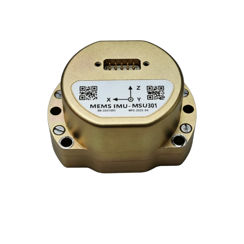
Applications
- Mobile mapping
- Track inspection
- Underwater high-precision Nav
- UAV attitude/path control
- Flight control
- Vehicle/vessel attitude
- Port survey
- SATCOM on the move
- Commercial vehicle IMU
Product Introduction
Company MSU301 series is a high-reliability, cost-effective six-axis MEMS inertial measurement module widely used in navigation, control, and measurement for vehicles, vessels, and UAVs. It employs domestically sourced gyroscopes and accelerometers in a rugged structure suited to long-duration vibration environments such as aerial surveying. The system applies full-temperature compensation for bias, scale factor, non-orthogonality errors, and acceleration-related terms, maintaining high measurement accuracy over extended operation.
Unique Technology
Company is a high-tech enterprise with full closed-loop capabilities from fiber winding equipment and coils to FOGs, fiber/MEMS inertial products, IMU circuits, software, and test equipment. End-to-end process control improves quality and reduces costs. Operating under ISO9001 with strict processes, it ensures product reliability and consistency.
MSU301 MEMS Inertial Measurement Module Performance Specifications
|
Parameter |
MSU301A |
MSU301B |
MSU301C |
|
Gyroscope |
|||
|
Range (°/s) |
±400 |
±400 |
±500 |
|
Full-Temperature Bias (°/h, 3σ) |
≤2 |
≤3 |
≤20 |
|
Bias Stability (°/h,10savg.) |
≤0.3 |
≤0.8 |
≤2 |
|
Bias Instability (°/h,allan, typ) |
≤0.03 |
≤0.08 |
≤0.1 |
|
Bias Repeatability (°/h) |
≤0.3 |
≤0.5 |
≤1 |
|
Angular Random Walk (°/√h) |
≤0.02 |
≤0.05 |
≤0.1 |
|
Scale Factor Nonlinearity (ppm) |
≤100 |
≤100 |
≤100 |
|
Cross-Coupling (rad) |
≤0.001 |
≤0.001 |
≤0.001 |
|
Bandwidth (Hz) |
≥200Hz |
≥200Hz |
≥200Hz |
|
Accelerometer |
|||
|
Range (g) |
±30 |
||
|
Full-Temperature Bias (mg, 3σ) |
≤2 |
||
|
Bias Stability (μg, 10s avg.) |
≤50 |
||
|
Bias Instability (μg, allan, typ) |
≤30 |
||
|
Bias Repeatability (μg) |
≤50 |
||
|
Velocity Random Walk (m/s/√h) |
≤0.03 |
||
|
Scale Factor Nonlinearity (ppm, ±1g) |
≤100 |
||
|
Cross-Coupling (rad) |
≤0.001 |
||
|
Bandwidth (Hz) |
≥200Hz |
||
|
Physical Characteristics |
|||
|
Power Supply (V) |
5~12 |
||
|
Steady-State Power (W) |
≤2 |
||
|
Start-Up Time (s) |
≤2 |
||
|
Update Rate (Hz, max) |
2000 |
||
|
Dimensions (mm × mm × mm) |
64.8×47×35.3 |
||
|
Weight (g) |
130±10 |
||
|
Operating Environment |
|||
|
Operating Temperature (°C) |
-40~80 |
||
|
Storage Temperature (°C) |
-55~85 |
||
|
Vibration (g, RMS) |
20~2000HZ, 6.06 |
||
|
Shock (g) |
500/1ms |
||
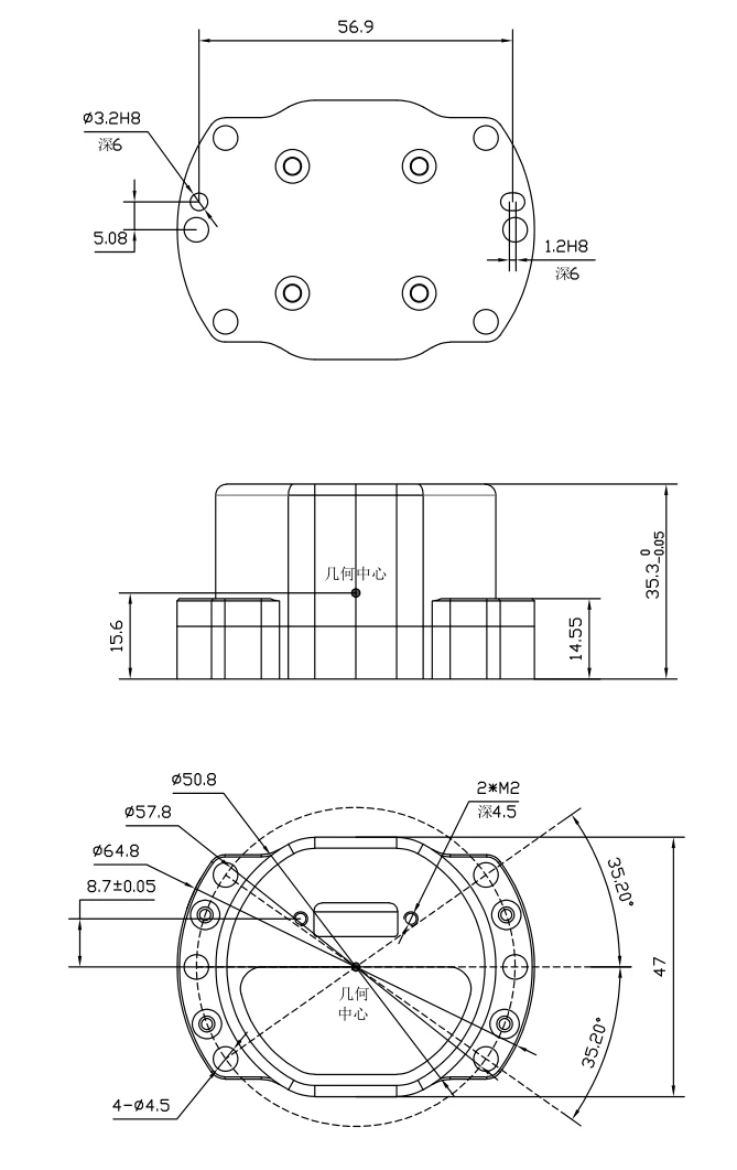
Mechanical Dimensions Diagram
Product Introduction
Product Overview
MSU301 series MEMS Inertial Measurement Module is a high-reliability, cost-effective six-axis MEMS inertial measurement module, widely used in navigation, control, and measurement for vehicles, vessels, and UAVs.MSU301AseriesInertial Measurement Module features domestically sourced Gyroscope and Accelerometer, with a rugged structural design suitable for precision measurement in prolonged vibration environments such as aerial surveying.The system incorporates full-temperature compensation for bias, scale factor, non-orthogonality, and acceleration-dependent errors, maintaining high measurement accuracy over extended periods.
Key Features
- High performance,high reliability
- -40°C to +80°C full-temperature calibration
- Gyro high-speed sampling and synchronous processing
- resistant to harsh mechanical environments
- in-system software upgrade capability
- drop-in replacement for HG4930
Applications
- Mobile mapping
- Track inspection
- Underwater high-precision navigation
- UAV attitude reference/path control
- Flight control
- Vehicle/vessel attitude measurement
- Port survey systems
- SATCOM on the move
- Commercial vehicle reference IMU
Technical Specifications
Table 1 MSU301 IMU Performance Specifications
|
Parameter |
MSU301A |
MSU301B |
MSU301C |
|
Gyro |
|||
|
Range (°/s) |
±400 |
±400 |
±500 |
|
Full-Temperature Bias (°/h, 3σ) |
≤2 |
≤3 |
≤20 |
|
Bias Stability (°/h,10savg.) |
≤0.3 |
≤0.8 |
≤2 |
|
Bias Instability (°/h,allan, typ) |
≤0.03 |
≤0.08 |
≤0.1 |
|
Bias Repeatability (°/h) |
≤0.3 |
≤0.5 |
≤1 |
|
Angular Random Walk (°/√h) |
≤0.02 |
≤0.05 |
≤0.1 |
|
Scale Factor Nonlinearity (ppm) |
≤100 |
≤100 |
≤100 |
|
Cross-Coupling (rad) |
≤0.001 |
≤0.001 |
≤0.001 |
|
Bandwidth (Hz) |
≥200Hz |
≥200Hz |
≥200Hz |
|
Accelerometer |
|||
|
Range (g) |
±30 |
||
|
Full-Temperature Bias (mg, 3σ) |
≤2 |
||
|
Bias Stability (μg, 10s avg.) |
≤50 |
||
|
Bias Instability (μg, allan, typ) |
≤30 |
||
|
Bias Repeatability (ug) |
≤50 |
||
|
Velocity Random Walk (m/s/√h) |
≤0.03 |
||
|
Scale Factor Nonlinearity (ppm, ±1g) |
≤100 |
||
|
Cross-Coupling (rad) |
≤0.001 |
||
|
Bandwidth (Hz) |
≥200Hz |
||
|
Physical Characteristics |
|||
|
Power Supply (V) |
5~12 |
||
|
Steady-State Power (W) |
≤2 |
||
|
Start-Up Time (s) |
≤2 |
||
|
Update Rate (Hz, max) |
2000 |
||
|
Dimensions (mm × mm × mm) |
64.8×47×35.3 |
||
|
Weight (g) |
130±10 |
||
|
Operating Environment |
|||
|
Operating Temperature (°C) |
-40~80 |
||
|
Storage Temperature (°C) |
-55~85 |
||
|
Vibration (g, RMS) |
20~2000HZ, 6.06 |
||
|
Shock (g) |
500/1ms |
||
Technical Specifications
Mechanical Characteristics
The MSU301 IMU features an aluminum alloy structure offering light weight, high structural strength, and resistance to vibration and shock. External dimensions are shown in Figure 1. The unit is secured with six M4 screws.
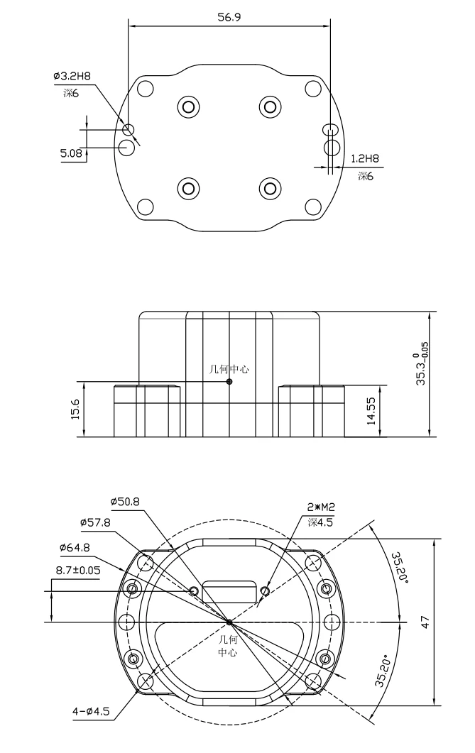
Fig.Fig. 1 Dimensions
Product Identification and Polarity
The product must be installed such that the carrier coordinate system remains in a fixed relationship with the target platform's carrier coordinate system. The MSU301A MEMS IMU carrier coordinate system is defined as follows.
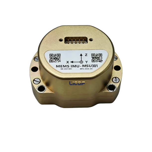
Fig. 2 Product Coordinate System
Interface Definition
The MSU301 IMU uses a custom CH-26A-10TJ dual-row pin header connector (mating connector: CH-26A-10ZJ) with 2.54 mm pin pitch, providing module power and external communication. The connector pinout is defined in Table 2.
Table 2 MSU301A IMU Connector Pinout
|
Pin |
Definition |
Remarks |
|
1 |
VSUP |
Power positive, +5~+12V |
|
2 |
COM1_Rx+ |
RS422-1 Receive + |
|
3 |
COM1_Tx+ |
RS422-1 Transmit + |
|
4 |
PPS IN+ |
GPS sync pulse receive + |
|
5 |
TOV+ |
Differential sync output + |
|
6 |
GND |
Power ground |
|
7 |
COM1_Rx- |
RS422-1 Receive - |
|
8 |
COM1_Tx- |
RS422-1 Transmit - |
|
9 |
PPS IN- |
GPS sync pulse receive - |
|
10 |
TOV- |
Differential sync signal output - |
External Communication
3.4.1 XDIMU-55AA Protocol
The XDIMU-55AA protocol outputs 40 bytes per frame in timed broadcast mode at a default output rate of 200 Hz and default baud rate of 460800 bps. Both the baud rate and output rate are configurable via host software. The data frame format: 1 start bit, 8 data bits, 1 stop bit, no parity, LSB first (little-endian/Intel format).
The system outputs a TOV sync pulse at the same frequency as the IMU sampling rate. The TOV pulse is differential, compatible with RS422 levels, and can be used as an external timestamp synchronization signal.
The system supports internal timestamp output requiring external GNSS time data and a PPS signal. GNSS time data enters via COM1-RX± in RS422 differential format at a default 460800 bps (synchronized with output baud rate). The COM1-RX± interface receives GPRMC sentence (compatible with GNRMC/GBRMC), PPS_IN± interface for PPS signal reception, PPS supports differential signal input, defaulting to falling-edge sync with 1 s period, as shown in Table 4.
Table 3 Communication Protocol Format
|
Pin |
Definition |
Remarks |
|
1 |
Header |
55H |
|
2 |
Header |
AAH |
|
3 |
Data Length |
N-4 |
|
4~N-1 |
Data |
|
|
N |
Checksum |
checksum |
|
Note: Checksum (checksum) is the lower 8 bits. |
||
Table 4 General IMU Protocol
|
No. |
Byte Index |
Byte Count |
Content |
Scale |
Range |
Unit |
Remarks |
|
1 |
0 |
1 |
0x55 |
1 |
Header |
||
|
2 |
1 |
1 |
0xAA |
1 |
Header |
||
|
3 |
2 |
1 |
36 |
1 |
Data Length |
||
|
4 |
3 |
4 |
PCnum |
1 |
1msCounter |
||
|
5 |
7 |
4 |
Angular RateX |
0.000001 |
[-2000,2000] |
°/s |
|
|
6 |
11 |
4 |
Angular RateY |
0.000001 |
[-2000,2000] |
°/s |
|
|
7 |
15 |
4 |
Angular RateZ |
0.000001 |
[-2000,2000] |
°/s |
|
|
8 |
19 |
4 |
AccelerationX |
0.000001 |
[-40g,40g] |
m/s2 |
|
|
9 |
23 |
4 |
AccelerationY |
0.000001 |
[-40g,40g] |
m/s2 |
|
|
10 |
27 |
4 |
AccelerationZ |
0.000001 |
[-40g,40g] |
m/s2 |
|
|
11 |
31 |
2 |
System Temperature |
0.008 |
[-120,120] |
℃ |
|
|
12 |
33 |
2 |
Date (YYYYMMDD) |
- |
- |
- |
Bit0~bit4day:0-31 Bit5~bit8month,0~12 Bit9~bit15year,0~99 e.g.1100011110011111 =2099year12month31day |
|
13 |
35 |
4 |
Timestamp |
0.1 |
- |
ms |
(h*3600+m*60+s*60)*10000 e.g.:00110011011101110101101010011111 =23h59min59.9999s |
|
14 |
39 |
1 |
Checksum |
1 |
[0,255] |
Index (2~38) of lower8bits |
Precautions
- Observe product electrical interface definitions. Strictly follow the terminal arrangement to avoid incorrect connections.
- This product is a precision measurement device. Avoid impacts, collisions, and other conditions beyond the product's rated tolerances during handling.
- Installation significantly affects angular rate measurement. To avoid mounting errors, the mounting surface must have good flatness.
- To ensure measurement accuracy, the product must be mounted securely to avoid measurement errors caused by looseness.
- Observe ESD protection during installation and use. Wearing an anti-static wrist strap is recommended.
- Operate strictly in accordance with this manual and verify that external conditions meet the specified requirements. Do not open the enclosure or modify the internal structure if issues arise. Contact our technical support team for assistance.
Hot Tags: msu301 mems inertial measurement module, China msu301 mems inertial measurement module manufacturers, factory