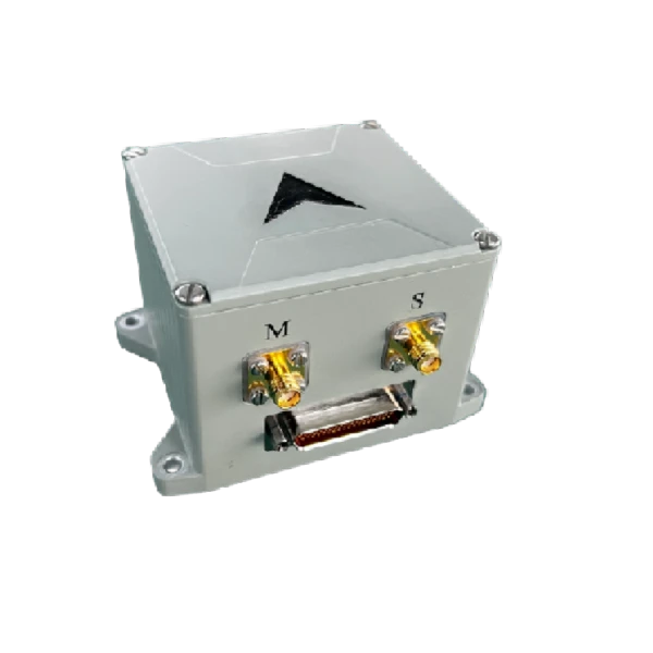
MSI300 MEMS_GNSS Combined Inertial Navigation System
Ultra-low power consumption of 3 W under steady operation
Zero velocity update and vehicle constraint algorithms for improved autonomous navigation accuracy
Description
Main Features
- Full-band GNSS support, high positioning and azimuth accuracy under complex environments
- Ultra-low power consumption of 3 W under steady operation
- Zero velocity update and vehicle constraint algorithms for improved autonomous navigation accuracy
Application Fields
- Attitude Control
- UAV & USV (Unmanned Aerial Vehicles & Unmanned Surface Vehicles)
- Intelligent Driving
Product Overview
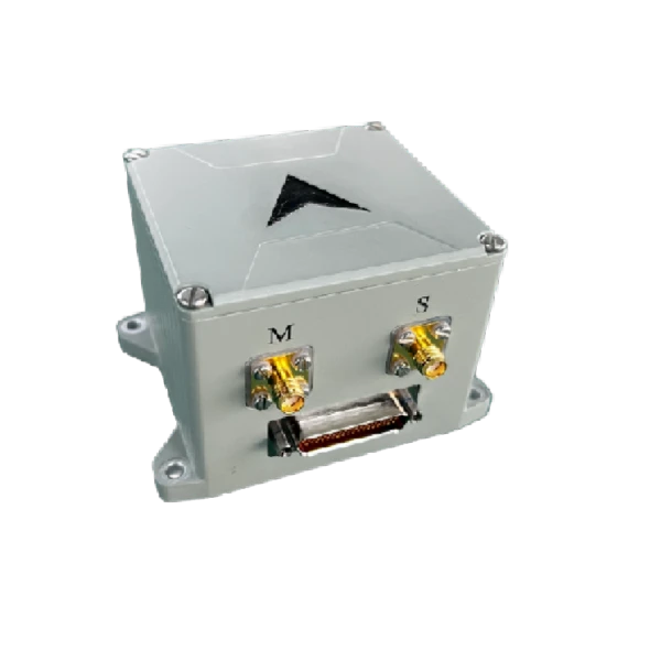
MSI300 is a high-precision, reliable and cost-effective MEMS GNSS/INS unit widely used in navigation, control and measurement for vehicles, vessels and UAVs. Its high-accuracy variants support automatic north-seeking, and multiple configurable modes are available to suit various carrier applications.
Unique Technology
Boasting mature modular design, the system's IMU consists of high-precision MEMS gyros and accelerometers. Compact, reliable and versatile, it fits various carrier navigation scenarios.
Its multi-sensor fusion filter processes GPS and MEMS INS data. Comparing their discrepancies and MEMS sensor drift/bias, a dedicated error model computes system errors in real time.
Real-time error compensation suppresses MEMS gyro integral drift, delivering stable high-precision attitude, velocity and position data for sustained long-term navigation performance.
Parameters
MSI100 MEMS_GNSS Combined Inertial Navigation System
|
Parameters |
Technical Specifications |
|||
|
MSI300 |
MSI300A |
MSI300C |
MSI300D |
|
|
Gyroscope |
||||
|
Range (°/s) |
±200 |
±400 |
±400 |
±300 |
|
Full-temperature Bias (˚/h, 3σ) |
≤0.3 |
≤2 |
≤30 |
≤80 |
|
Bias Stability (˚/h, 10s avg.) |
≤0.1 |
≤0.3 |
≤2 |
≤3 |
|
Accelerometer |
||||
|
Range (g) |
±10 |
±30 |
±30 |
±20 |
|
Full-temperature Bias (mg, 3σ) |
≤0.5 |
≤2 |
≤2 |
≤2 |
|
Bias Stability (μg, 10s avg.) |
≤20 |
≤50 |
≤50 |
≤50 |
|
Navigation Accuracy |
||||
|
Self-alignment North-Finding Accuracy (°, 1σ) |
≤0.5 |
≤3 |
/ |
/ |
|
Pure Inertial Accuracy (1σ, 60s, initial bias ignored) |
≤3m/60s |
≤5m/60s |
≤8m/60s |
≤10m/60s |
|
Physical Characteristics |
||||
|
Power Supply (V) |
9~36(ripple≤100mV) |
|||
|
Dimensions (mm×mm×mm) |
87×72×56 |
|||
|
Weight (g) |
370±20 |
|||
Product Introduction
Overview
MSI300 is a high-precision, high-reliability, cost-effective MEMS inertial navigation solution suitable for navigation, control, and measurement applications across various platforms including vehicles, vessels, and unmanned aerial vehicles. The high-precision variant features self-alignment capability and offers configurable modes to accommodate diverse carrier environments.
Features
- High Performance, Modular Design, and Light Weight
- Supports all GNSS frequency points with high positioning and orientation accuracy in complex environments
- Comprehensive interfaces and insulation isolation solutions
- Ultra-low power consumption of 4W during steady-state operation
- Fully calibrated and compensated across temperatures from -45℃ to +80℃
- Navigation solution supports automatic initialization alignment with accuracy better than 1°
- Resistant to harsh mechanical environments
- Features online software upgrade function and installation error compensation
- Self-correction algorithm maintains horizontal attitude accuracy when GNSS is unavailable
- Can access RTK differential
- Zero-speed correction and vehicle constraint algorithms improve autonomous navigation accuracy
Application
- Mobile measurement positioning and attitude reference
- Unmanned ground vehicles, unmanned surface vehicles, unmanned aerial vehicles
- Intelligent driving
Parameters
Table1MSI300 Performance Parameters
|
Parameters |
Technical Specifications |
|||
|
MSI300 |
MSI300A |
MSI300C |
MSI300D |
|
|
Gyroscope |
||||
|
Range (°/s) |
±200 |
±400 |
±400 |
±300 |
|
Full-temperature Bias (deg/h, 3σ) |
≤0.3 |
≤2 |
≤30 |
≤80 |
|
Bias Stability (deg/h, 10s avg.) |
≤0.1 |
≤0.3 |
≤2 |
≤3 |
|
Bias Instability ( °/h , Allan, typical) |
≤0.02 |
≤0.05 |
≤0.1 |
≤0.5 |
|
Bias Repeatability (°/h) |
≤0.1 |
≤0.3 |
≤2 |
≤3 |
|
Angular Random Walk (°/√h) |
≤0.01 |
≤0.02 |
≤0.1 |
≤0.025 |
|
Scale Factor Nonlinearity (ppm) |
≤100 |
≤100 |
≤100 |
≤100 |
|
Cross Coupling (rad) |
≤0.001 |
≤0.001 |
≤0.001 |
≤0.001 |
|
Bandwidth (Hz) |
≥50 |
≥200 |
≥200 |
≥200 |
|
Accelerometer |
||||
|
Range (g) |
±10 |
±30 |
±30 |
±20 |
|
Full-temperature Bias (mg, 3σ) |
≤0.5 |
≤2 |
≤2 |
≤2 |
|
Bias stability (μg, 10 s avg.) |
≤20 |
≤50 |
≤50 |
≤50 |
|
Bias Instability (μg, Allan, typical) |
≤10 |
≤30 |
≤30 |
≤30 |
|
Bias Repeatability (μg) |
≤20 |
≤50 |
≤50 |
≤60 |
|
Velocity Random Walk (m/s/√h) |
≤0.02 |
≤0.03 |
≤0.03 |
≤0.04 |
|
Scale Factor Non-Linearity (ppm, ±1g) |
≤100 |
≤100 |
≤100 |
≤100 |
|
Cross-coupling (rad) |
≤0.001 |
≤0.001 |
≤0.001 |
≤0.001 |
|
Bandwidth (Hz) |
≥50 |
≥200H |
≥200H |
≥200 |
|
Navigation Accuracy |
||||
|
Self-alignment North-Finding Accuracy (°, 1σ) |
≤0.5 |
≤3 |
/ |
/ |
|
Pure Inertial Accuracy (1σ, 60s, initial bias ignored) |
≤3m/60s |
≤5m/60s |
≤8m/60s |
≤10m/60s |
|
Depth Measurement Accuracy |
≤5cm |
≤5cm |
≤5cm |
≤5cm |
|
Combined Horizontal Position (m, 1σ) |
≤2 (single point), ≤0.02+1ppm (RTK) |
≤2 (single point), ≤0.02+1ppm (RTK) |
≤2 (single point), ≤0.02+1ppm (RTK) |
≤2 (single point), ≤0.02+1ppm (RTK) |
|
Combined Vertical Position (m, 1σ) |
≤3 (single point), ≤0.03+1ppm (RTK) |
≤3 (single point), ≤0.03+1ppm (RTK) |
≤3 (single point), ≤0.03+1ppm (RTK) |
≤3 (single point), ≤0.03+1ppm (RTK) |
|
Combined Horizontal Velocity (m/s, 1σ) |
≤0.05 |
≤0.05 |
≤0.05 |
≤0.05 |
|
Combined Vertical Velocity (m/s, 1σ) |
≤0.1 |
≤0.1 |
≤0.1 |
≤0.1 |
|
Combined Heading (°, 1σ, real-time) |
≤0.1 (baseline dual-antenna), ≤0.15 (single point, dynamic), ≤0.05 (RTK, dynamic), ≤0.03 (post-processing) |
≤0.1 (baseline dual-antenna), ≤0.15 (single point, dynamic), ≤0.05 (RTK, dynamic), ≤0.03 (post-processing) |
≤0.1 (baseline dual-antenna), ≤0.2 (single point, dynamic), ≤0.1 (RTK, dynamic), ≤0.05 (post-processing) |
≤0.1 (baseline dual-antenna), ≤0.2 (single point, dynamic), ≤0.1 (RTK, dynamic), ≤0.05 (post-processing) |
|
Combined Horizontal Attitude (degrees, 1σ, real-time) |
≤0.015 (single point, dynamic) ≤0.01 (RTK, dynamic) ≤0.007 (post-processing) |
≤0.015 (single point, dynamic) ≤0.01 (RTK, dynamic) ≤0.007 (post-processing) |
≤0.05 (single point, dynamic) ≤0.03 (RTK, dynamic) ≤0.01 (post-processing) |
≤0.05 (single point, dynamic) ≤0.03 (RTK, dynamic) ≤0.01 (post-processing) |
|
Physical Characteristics |
||||
|
Power Supply (V) |
9~36(ripple≤100mV) |
|||
|
Steady-State Power Consumption (W) |
≤4 |
|||
|
Startup Time (s) |
≤2 |
|||
|
Communication Interfaces |
RS-422/RS-232/CAN |
|||
|
Update Rate (Hz, max) |
200 |
|||
|
Dimensions (mm×mm×mm) |
87*72*56 |
|||
|
Weight (g) |
370±20 |
|||
|
Operating Environment |
||||
|
Operating Temperature (°C) |
-40 to +80 |
|||
|
Storage Temperature (℃) |
-55 to +85 |
|||
|
Vibration (g, RMS) |
20~2000Hz, 6.06 |
|||
|
Shock (g) |
500g/1ms |
|||
Technical Specifications
Structure
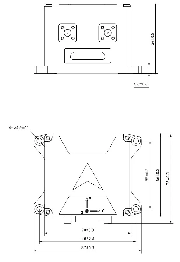
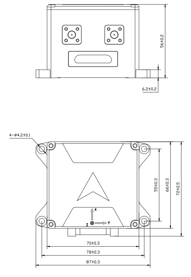
The mechanical interface of the MSI300 is shown in the figure:
Dimensions: 87mm×72mm×56mm (length×width×height, excluding connectors), with four through holes on the bottom surface fastened with M4 screws.
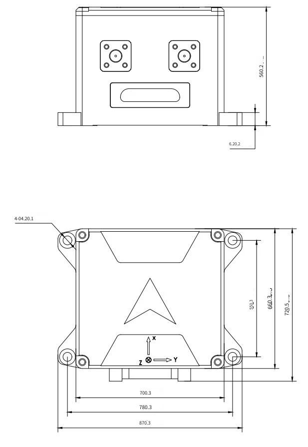
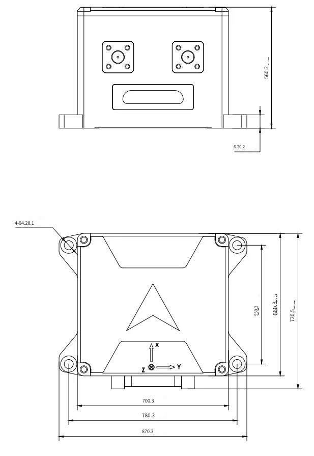
Figure1MSI300 Mechanical Interface Diagram
The GNSS receiver antenna is available in a standard model with dimensions: 110mm×110mm×171mm, and the base is secured using5×M6 screws.
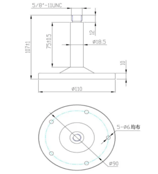
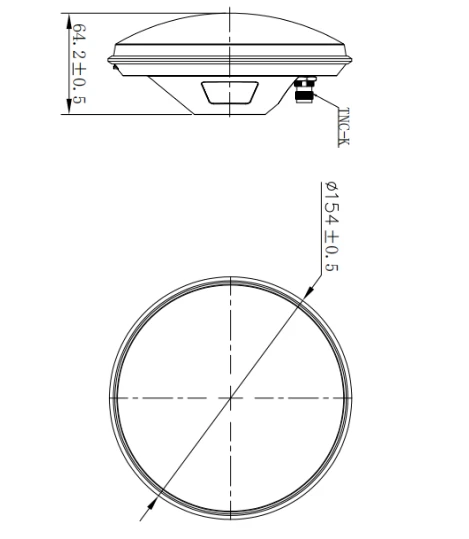
Figure3 MSI300 MEMS Integrated Navigation System Satellite Antenna Mechanical Interface Diagram
The GNSS receiver antenna features a strong magnetic base with dimensions of 100mm×100mm×66mm.
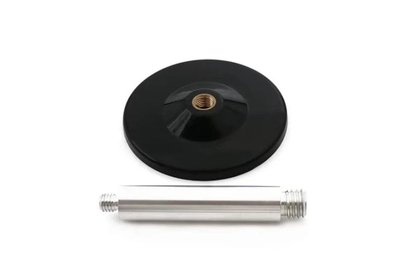
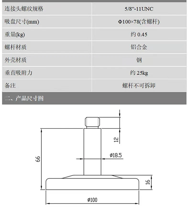
Figure4MSI300 Satellite Antenna Magnetic Base Diagram
Identification and Polarity
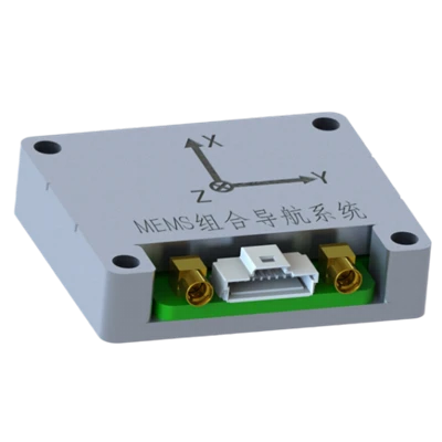
When the product is placed horizontally, the arrow indicates the X direction, and the output coordinate system is the "Forward, Right, Down" coordinate system.
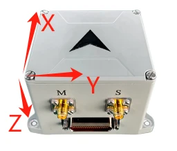
Figure4 Body Coordinate System Definition
Interface Definition
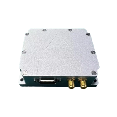
MSI300 external interface XS1 uses J30J-21ZKN-J. The dual-antenna connectors are standard SMA male ports, where S (left) is the auxiliary antenna and M (right) is the main antenna. The external interface definition is shown in the following table:
Table2MSI300 Interface Cable Pin Number Definition
|
J30JM-37ZKS Pin Number |
Connector Definition |
External DB9 |
Remark |
Function |
|
1 |
+24VIN |
External 24V power supply |
Red Clip |
power supply |
|
2 |
+24VIN |
|||
|
3 |
+24VGND |
Black Clip |
||
|
4 |
+24VGND |
|||
|
5 |
COM1_Rx+ |
External RS422 Isolated Interface 1 (software upgradable) |
DB9-M1-1 |
1. Upgrading software 2. Changing navigation configuration 3. Outputting navigation data |
|
6 |
COM1_Rx- |
DB9-M1-2 |
||
|
7 |
COM1_Tx+ |
DB9-M1-3 |
||
|
8 |
COM1_Tx- |
DB9-M1-4 |
||
|
9 |
GGND |
DB9-M1-5 |
||
|
13 |
COM2_Rx+ |
External Isolated RS422 Interface 2 |
DB9-M2-1 |
Output navigation data |
|
14 |
COM2_Rx- |
DB9-M2-2 |
||
|
15 |
COM2_Tx+ |
DB9-M2-3 |
||
|
16 |
COM2_Tx- |
DB9-M2-4 |
||
|
17 |
GGND |
DB9-M2-5 |
||
|
10 |
RS232_TXD1 |
External RS232 Isolated Interface 1 |
DB9-M3-2 |
Output navigation data |
|
11 |
RS232_RXD1 |
DB9-M3-3 |
||
|
12 |
GGND |
DB9-M3-5 |
||
|
24 |
RS232_TXD2 |
External RS232 Isolated Interface 2 |
DB9-M4-2 |
Output navigation data |
|
25 |
RS232_RXD2 |
DB9-M4-3 |
||
|
26 |
GGND |
DB9-M4-5 |
||
|
21 |
GPS_CFG_TXD |
Receiver Configuration RS232 Interface |
DB9-M5-2 |
1. Configure receiver board 1. Receiving differential data |
|
22 |
GPS_CFG_RXD |
DB9-M5-3 |
||
|
23 |
GGND1 |
DB9-M5-5 |
||
|
18 |
PPS_IN+ |
PPS differential input interface |
DB9-M6-1 |
Receiving external time synchronization signal |
|
19 |
PPS_IN- |
DB9-M6-2 |
||
|
20 |
GGND |
DB9-M6-5 |
||
|
29 |
PPS_OUT+ |
PPS differential output interface |
DB9-M7-3 |
Provides time synchronization signal |
|
30 |
PPS_OUT- |
DB9-M7-4 |
||
|
31 |
GGND |
DB9-M7-5 |
||
|
27 |
CANH |
External isolated CAN bus interface |
DB9-M8-7 |
Broadcast navigation data |
|
28 |
CANL |
DB9-M8-2 |
After the supply voltage drops below the device's operating threshold voltage, the power-off hold time tOFF before powering on again must be no less than 3s; insufficient power-off intervals may cause abnormal device startup, latch-up, or initialization failure.
External Communication
Integrated Navigation Data Protocol
MSI300 outputs data in default timed broadcast mode at an output frequency of 200Hz, with each data frame consisting of164bytes, baud rate 460800bps,1start bits,8bit data bits,1stop bits, no parity. For multi-byte variables, the low byte is transmitted first, followed by the high byte. The typical communication protocol is shown below; the communication protocol can also be customized according to user requirements.
Table 3 Integrated Navigation System Output Communication Protocol
|
No. |
First Byte Order |
Number of Bytes |
Signal Name |
Unit or Content |
Equivalent |
Description |
|
1 |
0 |
1 |
Frame Header1 |
Content: 55H |
1 |
8bit unsigned integer |
|
2 |
1 |
1 |
Frame Header2 |
Content: AAH |
1 |
8bit unsigned integer |
|
3 |
2 |
1 |
Data length |
Content: A0H |
1 |
8bit unsigned integer |
|
4 |
3 |
4 |
PCNum |
Interrupt counter |
1 |
32bit unsigned integer |
|
5 |
7 |
1 |
System status word |
- |
1 |
Self-checking: 0x10 Self-check passed: 0x12 Self-check error: 0x1F Coarse alignment: 0x33 Fine alignment: 0x35 Pure inertial navigation: 0x41 Zero velocity update: 0x43, Velocity + Position integration: 0x44 Velocity + Position + Heading integration: 0x45 Vehicle Constraint Navigation:0x46 Odometer integrated navigation:0x47 During self-calibration:0x51,0x53,0x55 Self-calibration complete, criterion valid:0x56 Self-calibration result written to Flash successfully:0x57 Self-calibration error:0x5F. |
|
6 |
8 |
1 |
Real-time status word |
- |
1 |
|
|
7 |
9 |
2 |
Reserved byte |
- |
1 |
|
|
8 |
11 |
4 |
Reserved byte |
- |
1 |
|
|
9 |
15 |
4 |
X Gyro angular rate |
[-1000,1000] °/s, |
0.0000005 |
Mean value within output period |
|
10 |
19 |
4 |
Y Gyro Angular Rate |
[-1000,1000] °/s, |
0.0000005 |
Mean value within output period |
|
11 |
23 |
4 |
Z Gyro Angular Rate |
[-1000,1000] °/s, |
0.0000005 |
Mean value within output period |
|
12 |
27 |
4 |
XAccelerometer Acceleration |
[-400m/s2,400m/s2] |
0.000001 |
Mean value within output period |
|
13 |
31 |
4 |
YAccelerometer Acceleration |
[-400m/s2,400m/s2] |
0.000001 |
Mean value within output period |
|
14 |
35 |
4 |
ZAccelerometer Acceleration |
[-400m/s2,400m/s2] |
0.000001 |
Mean value within output period |
|
15 |
39 |
4 |
Combined Longitude |
[-180,180]deg |
0.0000001 |
|
|
16 |
43 |
4 |
Combined Latitude |
[-90,90]deg |
0.0000001 |
|
|
17 |
47 |
4 |
Combined Altitude |
[-500,16384]m |
0.00001 |
|
|
18 |
51 |
2 |
Combined North Velocity |
[-1310,1310]m/s |
0.005 |
|
|
19 |
53 |
2 |
Combined Up Velocity |
[-1310,1310]m/s |
0.005 |
|
|
20 |
55 |
2 |
Combined East Velocity |
[-1310,1310]m/s |
0.005 |
|
|
21 |
57 |
2 |
Roll Angle |
[-90,90]deg |
0.006 |
|
|
22 |
59 |
2 |
Heading Angle |
[-180,180]deg |
0.006 |
North-by-West is positive |
|
23 |
61 |
2 |
Pitch Angle |
[-85,85]deg |
0.006 |
|
|
24 |
63 |
4 |
Satellite Longitude |
(-180,180]deg |
0.0000001 |
|
|
25 |
67 |
4 |
Satellite Latitude |
[-90,90]deg |
0.0000001 |
|
|
26 |
71 |
4 |
Satellite Altitude |
[-500,16384]m |
0.00001 |
|
|
27 |
75 |
2 |
Satellite North Velocity |
[-1310,1310]m/s |
0.005 |
|
|
28 |
77 |
2 |
Satellite Ground Speed |
[-1310,1310]m/s |
0.005 |
|
|
29 |
79 |
2 |
Satellite East Velocity |
[-1310,1310]m/s |
0.005 |
|
|
30 |
81 |
1 |
Temperature |
[-127,127] |
1 |
|
|
31 |
82 |
1 |
Positioning and Heading Validity |
/ |
1 |
bit0-3, receiver positioning flag: 00 Not positioning, 01 Single point positioning, 02 Float solution positioning, 03 Fixed solution positioning; bit4-7, heading signal: 00 Not heading, 01 Single-point heading, 02 Float solution heading, 03 Fixed solution heading. |
|
32 |
83 |
4 |
Satellite time of week (seconds) |
|||
|
33 |
87 |
1 |
Year |
|||
|
34 |
88 |
1 |
Month |
|||
|
35 |
89 |
1 |
Day |
|||
|
36 |
90 |
1 |
Number of positioning satellites |
[0,255] |
1 |
|
|
37 |
91 |
2 |
Satellite track angle |
[-180,180]deg |
0.006 |
|
|
38 |
93 |
2 |
Dual-Antenna Heading |
[-180,180]deg |
0.006 |
|
|
39 |
95 |
2 |
Reserved |
|||
|
40 |
97 |
14 |
Reserved |
|||
|
41 |
111 |
12 |
Reserved |
|||
|
42 |
123 |
4 |
AU |
m/s2 |
1 |
Upward acceleration |
|
43 |
127 |
4 |
AF |
m/s2 |
1 |
Forward acceleration |
|
44 |
131 |
4 |
AR |
m/s2 |
1 |
Rightward acceleration |
|
45 |
135 |
4 |
heave |
m |
1 |
Relative heave displacement |
|
46 |
139 |
4 |
Filtered output |
na |
1 |
|
|
47 |
143 |
4 |
Filtered input |
na |
1 |
|
|
48 |
147 |
4 |
Main frequency |
na |
1 |
|
|
49 |
151 |
4 |
Integer part of data time |
- |
- |
|
|
50 |
155 |
4 |
Fractional part of data time |
- |
- |
|
|
51 |
159 |
4 |
Reserved |
- |
1 |
|
|
52 |
163 |
1 |
Checksum |
Low byte of the cumulative sum of data length and data bytes8bit |
1 |
Precautions
- Pay attention to the product's electrical interface definition; when in use, strictly follow the pin arrangement to avoid incorrect connections.
- This product is a precision measurement device. During operation, take care to avoid impacts, collisions, and other conditions that exceed the product's tolerance range.
- The installation of the product has a significant effect on angular velocity measurement. To avoid introducing installation errors, the mounting surface must have good flatness.
- To ensure measurement accuracy, the product must be installed securely and reliably to prevent measurement errors caused by looseness.
- During installation and use of the product, attention should be paid to electrostatic protection. Wearing an anti-static wrist strap is recommended.
- Please operate strictly in accordance with the requirements of this manual and confirm that the external environment is consistent with the usage requirements. If a problem occurs, do not remove the cover or alter the internal structure of the product. If you have any issues, please contact our technical staff promptly.
Hot Tags: msi300 mems_gnss combined inertial navigation system, China msi300 mems_gnss combined inertial navigation system manufacturers, factory