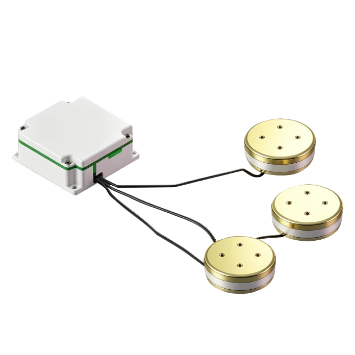
FT120H Three-Axis FOG
All-Solid-State Design
Strong Environmental Adaptability
High Reliability, Ultra-Long Lifetime
Description
Main Features
- Miniature Compact Design
- All-Solid-State Design
- Strong Environmental Adaptability
- High Reliability, Ultra-Long Lifetime
- Fully DigitalRS-422 Electrical Interface Output
Application Fields
- EO Pod
- Flight Control Platform
- Optical/Photography Platform
- Platform Stabilization Device
- SatCom-on-the-Move
- Inertial Measurement Unit
- Lightweight UAV
Product Overview
The FT120H is a Sagnac-effect inertial angular rate sensor measuring angular velocity along its sensitive axis. Its sensing unit is a fiber coil. A digital closed-loop detection circuit extracts the optical path difference caused by external angular velocity and converts it into a voltage signal for closed-loop feedback and control, achieving signal modulation and demodulation for high-precision detection. The FT120H three-axis integrated FOG consists of an optical sensing unit and signal detection, providing angular increment and temperature data for medium-high precision INS, positioning, and servo stabilization systems.
Unique Technology
Company is a high-tech enterprise with full closed-loop capabilities from fiber winding equipment and coil winding to IMU circuits, software, and test equipment. End-to-end process control improves quality and reduces costs. Operating under ISO9001 with strict processes, it ensures product reliability and consistency. The FT120H three-axis integrated FOG is designed for underwater UUV INS. Underwater environments lack satellite signals, so UUVs rely on pure inertial navigation for long-duration attitude and position calculation, demanding strict long-term low drift performance. Featuring excellent bias stability, the product continuously outputs high-precision angular increment and temperature data, effectively reducing cumulative errors during long missions and meeting autonomous orientation and attitude measurement needs for underwater cruise and seabed mapping.
FT120H Three-Axis FOG
FT120H Three-Axis FOG Performance Parameters
|
Parameter |
FT120H |
|
Start-up Time(s) |
3 |
|
Bias(°/h) |
≤0.25 |
|
Room Temp.(Constant Temp.)Bias Stability(10s avg. ,°/h) |
≤0.003 |
|
Room Temp.(Constant Temp.)Bias Stability(100s avg. ,°/h) |
≤0.001 |
|
Variable Temp. Bias Stability(1℃/min ,100s avg. ,°/h) |
≤0.005 |
|
Bias Repeatability(°/h) |
≤0.001 |
|
Bias Magnetic Sensitivity(°/h/Gs) |
≤0.003 |
|
Angle Random Walk(°/h1/2) |
≤0.0002 |
|
Scale Factor Nonlinearity(ppm) |
≤2 |
|
Scale Factor Asymmetry(ppm) |
≤2 |
|
Scale Factor Repeatability(ppm) |
≤5 |
|
Threshold(°/h) |
≤0.001 |
|
Resolution(°/h) |
≤0.001 |
|
Bandwidth(Hz) |
≥200 |
|
Operating Temperature(℃) |
-45~+70 |
|
Storage Temperature(℃) |
-55~+85 |
|
Dynamic Range(°/s) |
±300 |
|
Supply Voltage(V) |
+5 |
|
Room Temp. Steady-State Power Consumption(W) |
≤4.5 |
|
Full-Temp. Steady-State Power Consumption(W) |
≤8 |
|
Start-up Inrush Current(A) |
<2 |
|
Dimensions(mm) |
(Electronic Box)60±×60×28.0/(Sensor Head)⌀120×30.9 |
|
Weight(g) |
<2300(Excluding Base) |
Dimensional Drawing
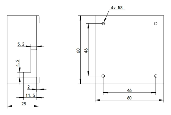
Electronic Box Section
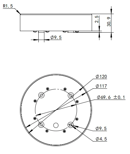
Sensor Head Section
Overview
This document specifies the requirements and methods for the use and maintenance of the FT120H high-precision three-axis Fiber Optic Gyroscope (FOG) (hereinafter referred to as "the product").
Product Description Working Principle, Functions, and Scope of Application
Working Principle
The product is an inertial angular rate sensor based on the optical Sagnac effect, used to measure the angular velocity of a vehicle along the product's sensitive axes. The angular velocity sensing unit is a fiber coil. A digital closed-loop detection circuit extracts the optical path difference between clockwise (CW) and counterclockwise (CCW) propagating light induced by external physical angular velocity in the fiber coil, while converting the optical path difference signal into a voltage signal for closed-loop feedback and control, thereby achieving signal modulation and demodulation for high-precision angular velocity detection.
Functions
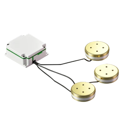
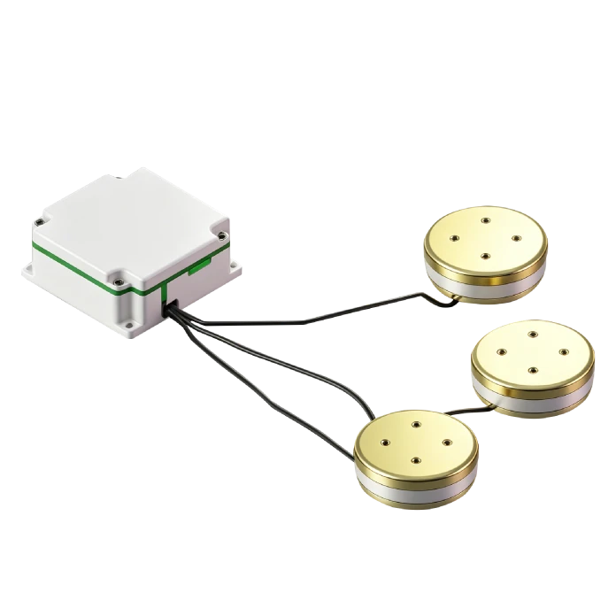
The product consists of an optical angular velocity sensing unit and a signal detection unit, providing three-axis angular increment data and internal temperature information.
Scope of Application
The product is primarily applicable to medium-to-high precision inertial navigation systems (INS), positioning and orientation systems, servo stabilization systems, and similar applications.
Composition
The main components of the product are as follows:
Circuit box: includes Erbium-Doped Fiber (EDF) light source, signal detection and control circuit, fiber coupler, and photodetector;
Sensor head: includes fiber coil and Y-waveguide;
FOG structural components and shielding enclosure.
Dimensions and Mounting
Outline Dimensions
Circuit box outline dimensions (mm): 60 ± 0.1 × 60 ± 0.1 × 28.0 ± 0.1 (length × width × height);
Sensor head outline dimensions (mm): Φ120 ± 0.1 × 30.9 ± 0.1;
Mounting Dimensions
Circuit box mounting dimensions (mm): 46 ± 0.1 × 46 ± 0.1 (length × width), 4 × M3;
Sensor head mounting dimensions (mm): Φ69.6 ± 0.1, 4 mounting holes: Φ4.5;
As shown in Figure 1.
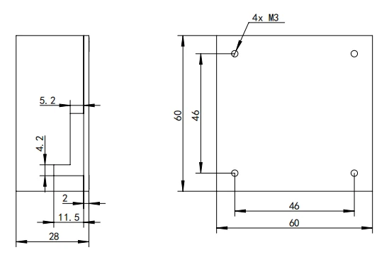
(a) Circuit Box
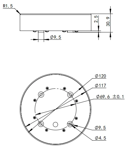
(b) Sensor Head
Figure 1 FT120H FOG Assembly Outline and Mounting Diagram
Weight
Total product weight: < 2300 g (excluding platform).
Main Performance Parameters
The main performance parameters of the product are detailed in Table 1.
Table 1 Main Performance Parameters
|
No. |
Test Item |
Specification |
|
1 |
Start-up Time (s) |
3 |
|
2 |
Bias (°/h) |
≤0.25 |
|
3 |
Bias Stability at Room Temperature (constant temp., 10 s smoothing, °/h) |
≤0.003 |
|
Bias Stability at Room Temperature (constant temp., 100 s smoothing, °/h) |
≤0.001 |
|
|
4 |
Bias Stability under Temperature Variation (1 °C/min ramp, 100 s smoothing, °/h) |
≤0.005 |
|
5 |
Bias Repeatability (°/h) |
≤0.001 |
|
6 |
Bias Magnetic Sensitivity (°/h/Gs) |
≤0.003 |
|
7 |
Random Walk Coefficient (°/h½) |
≤0.0002 |
|
8 |
Scale Factor Nonlinearity (ppm) |
≤2 |
|
9 |
Scale Factor Asymmetry (ppm) |
≤2 |
|
10 |
Scale Factor Repeatability (ppm) |
≤5 |
|
11 |
Threshold (°/h) |
≤0.001 |
|
12 |
Resolution (°/h) |
≤0.001 |
|
13 |
Bandwidth (Hz) |
≥200 |
|
14 |
Operating Temperature (°C) |
-45~+70 |
|
15 |
Storage Temperature (°C) |
-55~+85 |
|
16 |
Dynamic Range (°/s) |
±300 |
|
17 |
Supply Voltage (V) |
+5 |
|
18 |
Steady-State Power Consumption at Room Temperature (W) |
≤4.5 |
|
19 |
Steady-State Power Consumption (full temp. range, W) |
≤8 |
|
20 |
Start-up Inrush Current (A) |
<2 |
Mechanical and Electrical Interfaces
Power Supply Requirements
The product is powered by a +5 V DC power supply. The power supply requirements are shown in Table 2:
Table 2 FT120H FOG Power Supply Requirements
|
No. |
Item |
Requirement |
|
1 |
Power Supply Accuracy |
±5% |
|
2 |
Power Supply Ripple (Vpp) |
≤50mV |
|
3 |
Supply Current |
>2A |
Electrical Connection Interface
The FOG-side connector model is J30JZLN9ZKWA000. A mating connector (model: J30JZ/XN9TJCAL01) is provided. The pin definitions are given in Table 3.
Table 3 J30JZLN9ZKWA000 FOG Connector and Test Point Definitions
|
Pin No. |
Definition |
Remarks |
|
1 |
+5V |
Power Input |
|
2 |
GND |
Power Ground |
|
3 |
Reserved |
-- |
|
4 |
RXD+ |
FOG Differential Strobe Positive |
|
5 |
TXD+ |
FOG RS422 Output Positive |
|
6 |
+5V |
Power Input |
|
7 |
GND |
Power Ground |
|
8 |
RXD- |
FOG Differential Strobe Negative |
|
9 |
TXD- |
FOG RS422 Output Negative |
Note: When connecting to or handling the product, ESD protection measures shall be taken in accordance with GJB 1649-1993.
Communication Protocol
Communication interface: Both RXD and TXD are RS422/485 differential communication interfaces. RXD is used to receive a differential pulse (or square wave) synchronization strobe signal, and TXD is used for serial data signal output.
Communication protocol: After receiving the falling edge of the strobe signal, the FOG latches the internal angular increment data and begins outputting the gyro data packet via TXD within 1 μs. The baud rate is 460.8 kbps. The data packet contains 23 bytes, each consisting of 1 start bit, 8 data bits, and 1 stop bit, with no parity bit.
The angular increment data represents the accumulated angular displacement of the gyro between two consecutive strobe signals. The average angular velocity over a given time period is obtained by dividing the accumulated angular increment value by the corresponding time interval.
The data packet format is as follows:
Table 4 Gyro Data Packet Format
|
Byte No. |
Content |
|
99 (Hexadecimal) |
|
|
66 (Hexadecimal) |
|
|
Status Word, normal value: FF (hexadecimal) |
|
|
X-axis Gyro Angular Increment 1, LSB |
|
|
X-axis Gyro Angular Increment 2 |
|
|
X-axis Gyro Angular Increment 3 |
|
|
X-axis Gyro Angular Increment 4, MSB |
|
|
Y-axis Gyro Angular Increment 1, LSB |
|
|
Y-axis Gyro Angular Increment 2 |
|
|
Y-axis Gyro Angular Increment 3 |
|
|
Y-axis Gyro Angular Increment 4, MSB |
|
|
Z-axis Gyro Angular Increment 1, LSB |
|
|
Z-axis Gyro Angular Increment 2 |
|
|
Z-axis Gyro Angular Increment 3 |
|
|
Z-axis Gyro Angular Increment 4, MSB |
|
|
Temperature Data 1, LSB |
|
|
Temperature Data 1, MSB |
|
|
Temperature Data 2, LSB |
|
|
Temperature Data 2, MSB |
|
|
Temperature Data 3, LSB |
|
|
Temperature Data 3, MSB |
|
|
Frame Number, increments by 1 on each transmission, cyclic count |
|
|
Checksum, cumulative sum of Byte 3 through Byte 22 |
|
|
Note: Temperature dimension is 16. |
|
The status word bit definitions are as follows:
Table 5 Gyro Status Word Data Format
|
bit7 |
bit6 |
bit5 |
bit4 |
bit3 |
bit2 |
bit1 |
bit0 |
|
Reserved |
Z-axis Circuit Control Status |
Y-axis Circuit Control Status |
X-axis Circuit Control Status |
Reserved |
Z-axis Optical Path Status |
Y-axis Optical Path Status |
X-axis Optical Path Status |
Where: the "Reserved" bits are always 1;
the "Circuit Control Status" bit set to 1 indicates normal FOG circuit control status; set to 0 indicates an abnormal control status;
the "Optical Path Status" bit set to 1 indicates normal FOG optical path operation; set to 0 indicates an abnormal optical path status.
If during FOG operation either of the above two status bits remains 0, accompanied by abnormal gyro data, the FOG shall be returned for repair.
Product Installation and Removal
Requirement
The user is responsible for installing and removing the product. During this process, the product must not be subjected to impact, striking, or collision, nor shall any mechanical processing be performed on its external surfaces.
a) The flatness of the mounting surface shall be better than 0.02 mm;
b) During product testing, it is recommended to fully consider the heat dissipation of the product mounting base.
Post-Installation Inspection
Verify that all mounting screws conform to the mounting hole dimensions and are securely fastened.
Operating Procedures
Pre-Use Inspection
Inspect the product for physical damage such as collision marks.
Product Usage Instructions
Mount the product on the vehicle and correctly connect the cables in accordance with Table 3;
Establish the data connection per the communication protocol specified in Section 2.6.3.
Precautions
a) The FOG should not be subjected to frequent power on/off cycling during use, as this may degrade FOG performance and shorten its service life;
b) Before powering on the FOG, inspect the power supply system to ensure that the supply voltage is correct and that no short circuits exist between electrical points of the power supply, or between the FOG housing and any electrical points;
c) If the product exhibits abnormal operation, consult the manufacturer. Unauthorized disassembly and repair are strictly prohibited;
d) The FOG is a precision instrument. Handle with care during use and transportation;
e) Ensure correct connection of product input signal lines, output signal lines, and power supply lines;
f) ESD protection measures shall be taken when handling the product;
g) The ambient magnetic field strength at the product location shall be less than 10 Gauss.
Maintenance
Prior to installation on the vehicle, the product shall be powered on at least once every 6 months for a duration of 3600 s. Electrical parameter testing is not required during this power-on period;
After installation on the vehicle, the product shall be powered on at least once per year for a duration of 3600 s. Electrical parameter testing is not required during this power-on period.
Transportation and Storage Requirements
Transportation Precautions
Place the product according to the orientation indicated on the packaging box;
Transportation is permitted by road, rail, air, and water;
Ensure the packaging box is securely fastened to the carrier to prevent movement during transport.
Storage Conditions, Shelf Life, and Precautions
a) Products placed in packaging boxes shall be stored under standard atmospheric pressure conditions. The storage ambient temperature shall be 25 °C ± 10 °C, relative humidity 30%–50%, and the surrounding magnetic field strength shall be less than 10 Gauss;
b) The product shelf life is 15 years.
Unpacking Instructions
Inspect the outer packaging for physical damage such as collision marks;
Verify that the product and all accessories are complete, as detailed in Table 7.
Perform ESD protection procedures when removing the product.
Table 7 Product Delivery Checklist
|
No. |
Item |
Quantity |
|
1 |
FT120H FOG Assembly |
1 |
|
2 |
FOG Assembly Packaging Box |
1 |
|
3 |
FOG Assembly Test Report |
1 |
|
4 |
J30JZ/XN9TJCAL01 Connector |
1 |
|
5 |
Certificate of Conformity |
1 |
Hot Tags: ft120h three-axis fog, China ft120h three-axis fog manufacturers, factory